ON OFF Valve Preventive Maintenance and Testing Procedure
In this article, you will learn how to do preventive maintenance and testing procedure of on off valve used in the industry.
We will discuss all important activities which should be carried out in every scheduled PM job.
Prerequisites of the PM job are:
Each tag whose PM is to be done should have a unique work permit
Following Test and Calibration Instruments (TCI =Test and Calibration Instruments) are necessary
Digital Multimeter
Tool bag with all necessary tools
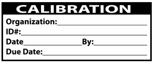
The above tools must be pre-calibrated with must have proper validity to use them in our calibration and maintenance activity. Always verify TCI’s validity which is mentioned in the calibration sticker which is attached to each instrument.
The TCI’s validity should not be overdue. A sample calibration sticker is shown below. The calibration sticker shows important information like the instrument tag, calibration date, and due date.
All mandatory personal protective equipment (PPE) and special PPE are to be kept ready before proceeding with the job.
Note down the fail action of the on-off valve and Air Filter Regulator (AFR) set pressure from the data sheet of the valve.
Preventive Maintenance Procedure for ON OFF Valve
Take appropriate work permits and verify all details in the permit. Take necessary approvals.
Inform operation engineers regarding the testing activity that we will carry out during the PM job so that they can prepare accordingly.
We may do ON and OFF the valve for testing purposes. We have to bypass the logic if any exists and update the log register.
The first step is to check the air pressure in the AFR and confirm the air pressure value with the air pressure mentioned in the datasheet. if not then adjust the pressure in the AFR accordingly.
Now using a snoop liquid leak detector (or any other leak detector) check the instrument tubing and all the connections for the air leakage test.
You can remove the solenoid power from the control room either by forcing the logic or by removing the fuse/relay/barrier.
Open the solenoid’s (SOV) cover. Disconnect the solenoid coil termination.
Check the resistance of the solenoid coil. The coil resistance value must be in the healthy range. You can find the correct resistance value from the solenoid manual or from the previous calibration record.
If the coil is healthy then restore the solenoid connections and then restore the power to the solenoid. (Take all necessary precautions while working with the power)
Check the valve feedback cable’s connection tightness and healthiness.


View Comments
its very nice & good information which you are sharing to us &it is very help full
thanks
I suggest to call it a function test PM rather than calibration.