Learn how to program an OMRON PLC for a car parking system application for gate open and close operations based on sensor inputs.
Car Parking System Application
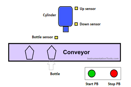
Car parking systems generally have 2 Gates, namely the Gate to enter the parking area and the Gate to exit the parking area. The Gate will OPEN/UP when it detects a car going through it and it will again CLOSE/DOWN after the car passes through the Gate. The number of cars entering and exiting the parking area will be counted.
PLC Logic
This Car Parking System program has 3 main buttons, the START_SYSTEM (0.00) button is used to turn ON the system, the STOP_SYSTEM (0.01) button is used to turn OFF the system, and the RESET_COUNTER (0.02) button is used to Reset the Counter to Zero “0”.
Each Gate has 4 Sensors, for example on ‘Gate IN’ the SENS_CAR_IN1 (0.03) Sensor functions to detect an incoming car, when the SENS_CAR_IN1 (0.03) Sensor is Active it will Activate the GATE_IN_UP Output (100.00) so that the Gate opens/rises. The gate will Stop opening/rising when the LS_GATE_IN_UP Sensor (0.07) is Active, the LS_GATE_IN_UP Sensor (0.07) functions as a limiter for the highest point of the Gate.
After the car passes the gate, the SENS_CAR_IN2 sensor (0.04) will be Active for a moment and Activate the GATE_IN_DOWN output (100.01). The Gate closes/descends again and will Stop descending when the LS_GATE_IN_DOWN Sensor (0.08) is Active.
The LS_GATE_IN_DOWN (0.08) sensor functions as a limiter for the lowest point of the Gate. COUNTER (D0) will count incoming cars (+1) when the SENS_CAR_IN1 Sensor (0.03) is Active. ‘Gate OUT’ has the same working system as ‘Gate IN’, the difference is that when a car is detected leaving, the data from COUNTER (D0) will decrease (-1). Data from COUNTER (D0) will decrease when LS_GATE_OUT_DOWN (0.10) is Active.
This program has an Alarm function, when there is a problem with the Gate Electric Motor then the TRIG_ALARM_IN (1.00) or TRIG_ALARM_OUT (1.01) input is Active so that the GATE_IN_ALARM (100.04) or GATE_OUT_ALARM (100.05) output will be Active.
Inputs and Outputs
Addressing Input, Output, TIM, Bit Memory, and Word Memory details are as follows.
| Comment | Input (I) | Output(Q) | Word Memory | Memory Bits |
| START_SYSTEM | 0.00 | |||
| STOP_SYSTEM | 0.01 | |||
| RESET_COUNTER | 0.02 | |||
| SENS_CAR_IN1 | 0.03 | |||
| SENS_CAR_IN2 | 0.04 | |||
| SENS_CAR_OUT1 | 0.05 | |||
| SENS_CAR_OUT2 | 0.06 | |||
| LS_GATE_IN_UP | 0.07 | |||
| LS_GATE_IN_DOWN | 0.08 | |||
| LS_GATE_OUT_UP | 0.09 | |||
| LS_GATE_OUT_DOWN | 0.10 | |||
| TRIG_ALARM_IN | 1.00 | |||
| TRIG_ALARM_OUT | 1.01 | |||
| COUNTER | D0 | |||
| IR_SYSTEM | W0.00 | |||
| IR_GATE_IN_UP | W0.01 | |||
| IR_GATE_IN_DOWN | W0.02 | |||
| IR_GATE_OUT_UP | W0.03 | |||
| IR_GATE_OUT_DOWN | W0.04 | |||
| IR_ALARM_GATE_IN | W0.05 | |||
| IR_ALARM_GATE_OUT | W0.06 | |||
| GATE_IN_UP | 100.00 | |||
| GATE_IN_DOWN | 100.01 | |||
| GATE_OUT_UP | 100.02 | |||
| GATE_OUT_DOWN | 100.03 | |||
| GATE_IN_ALARM | 100.04 | |||
| GATE_OUT_ALARM | 100.05 |
OMRON PLC Programming
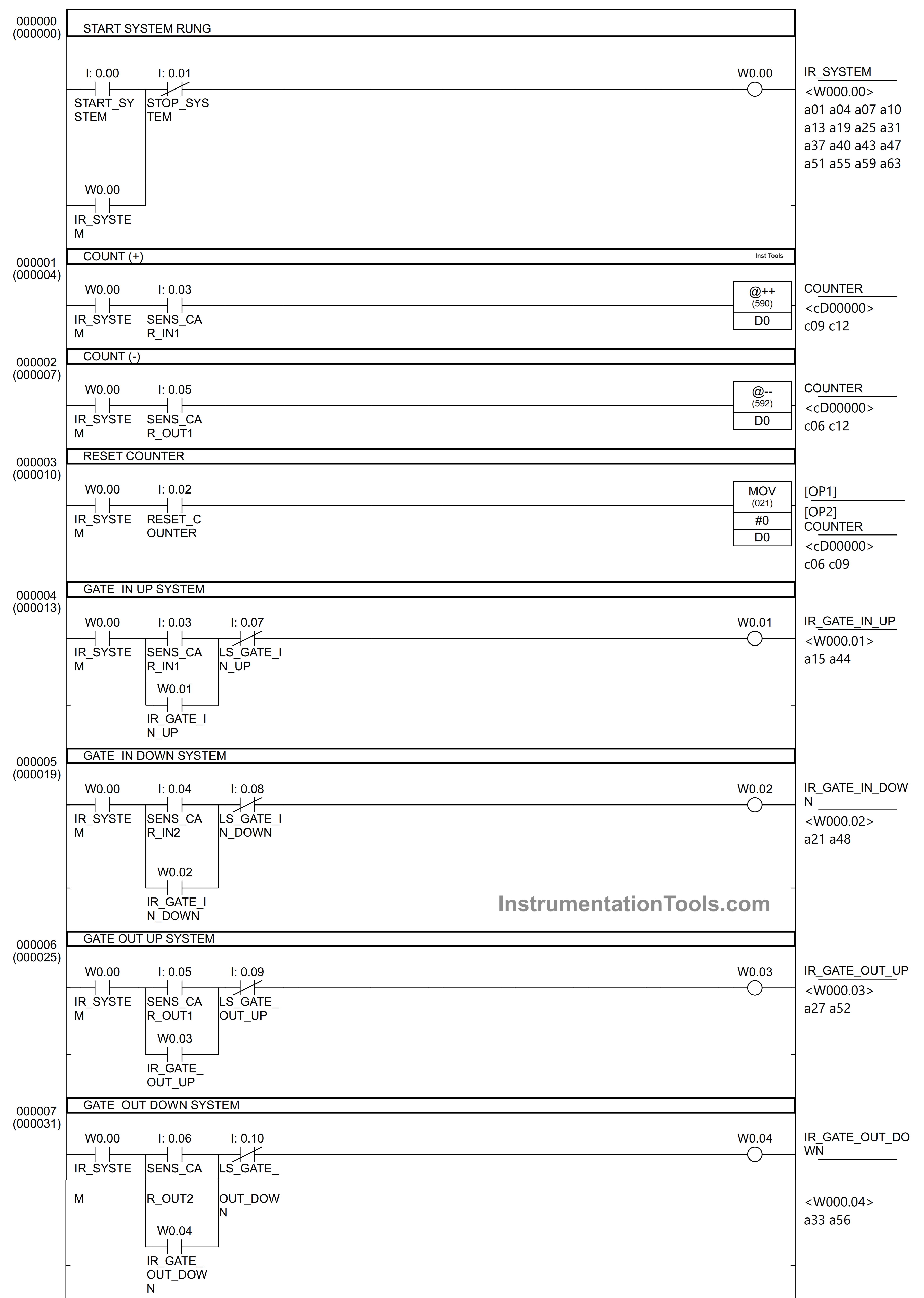
RUNG 0 (START SYSTEM RUNG)
This Rung functions to Activate and Deactivate the entire system. When the START_SYSTEM (0.00) button is pressed then Coil IR_SYSTEM (W0.00) is Active.
Because of the latching function of the coil IR_SYSTEM (W0.00) then even if the START_SYSTEM (0.00) button is released, the system will remain Active. The IR_SYSTEM (W0.00) Coil will only switch OFF when the STOP_SYSTEM (0.01) contact is Active.

RUNG 1 (COUNT(+))
This Rung serves as an up-counter for cars entering the parking area. When the IR_SYSTEM (W0.00) and SENS_CAR_IN1 (0.03) Inputs are ON, the COUNTER (D0) will increase by +1 using the “@++”/Binary Increment instruction.
RUNG 2 (COUNT(-))
This Rung serves as a down counter for the cars leaving the parking area. When the IR_SYSTEM (W0.00) and SENS_CAR_OUT1 (0.05) are Active then the COUNTER (D0) will decrease by -1 using the instruction “@–”/Binary Decrement.
RUNG 3 (RESET COUNTER)
This rung has a function to Reset data in the COUNTER (D0). When the IR_SYSTEM (W0.00) and the RESET_COUNTER (0.02) are Active, the COUNTER (D0) will become zero ‘0’ because the MOV instruction is used to move the value ‘0’ to the memory address Word COUNTER (D0).
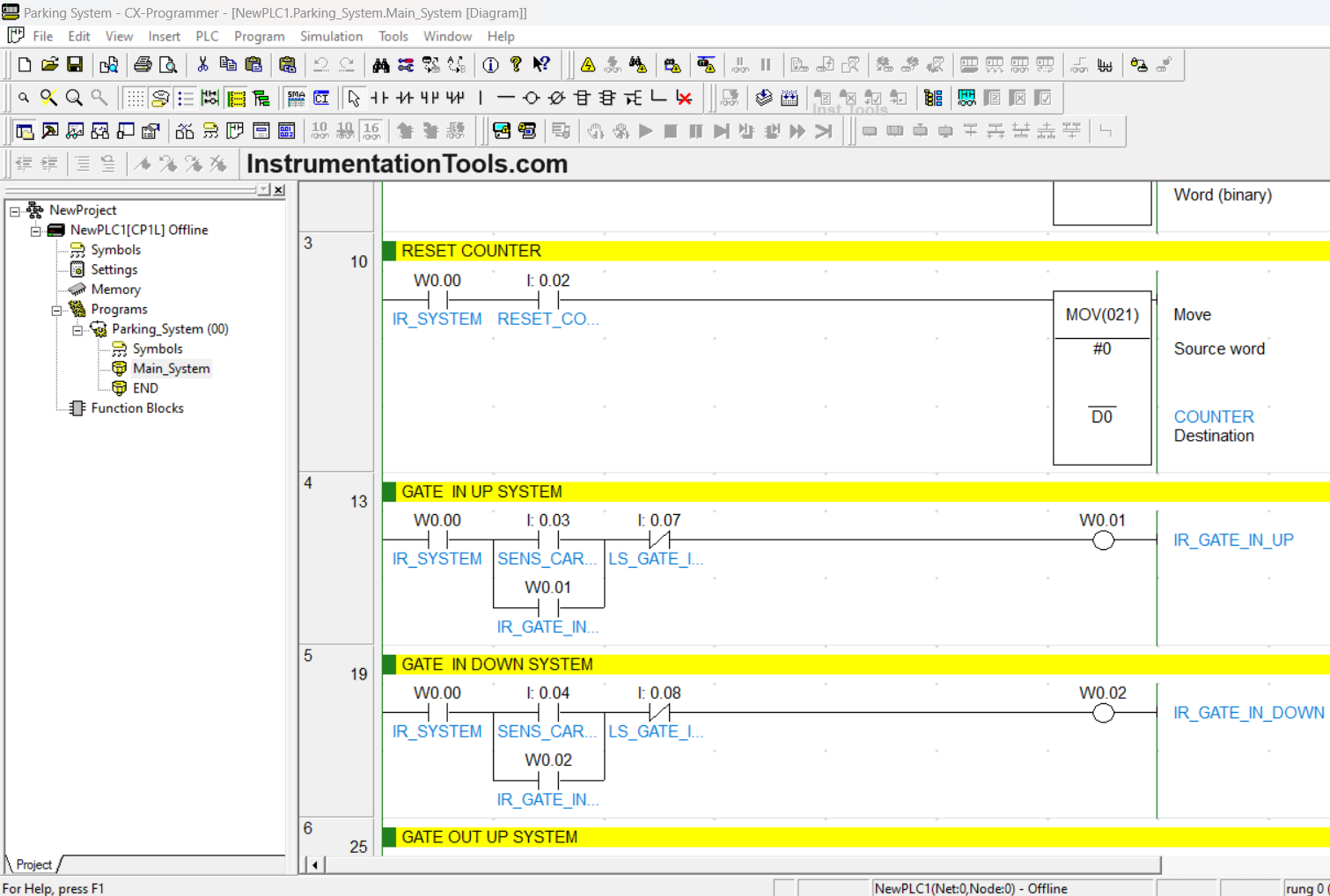
RUNG 4 (GATE IN UP SYSTEM)
Rung 4 has a function to open/raise “Gate IN”. When the IR_SYSTEM (W0.00) and SENS_CAR_IN1 (0.03) are Active, then the IR_GATE_IN_UP (W0.01) coil will be Active.
Coil IR_GATE_IN_UP (W0.01) will be disabled when contact LS_GATE_IN_UP (0.07) is Active. Coil IR_GATE_IN_UP (W0.01) has an Interlock function so that if Input SENS_CAR_IN1 (0.03) is disabled, Coil IR_GATE_IN_UP (W0.01) is still Active.
RUNG 5 (GATE IN DOWN SYSTEM)
Rung 5 has a function to close/lower “Gate IN”. When the IR_SYSTEM (W0.00) and SENS_CAR_IN2 (0.04) are Active, then the IR_GATE_IN_DOWN (W0.02) coil will be Active.
Coil IR_GATE_IN_DOWN (W0.02) will be disabled when contact LS_GATE_IN_DOWN (0.08) is Active. Coil IR_GATE_IN_DOWN (W0.02) has an Interlock function so that if Input SENS_CAR_IN2 (0.04) is deactivated Coil IR_GATE_IN_DOWN (W0.02) is still Active.
RUNG 6 (GATE OUT UP SYSTEM)
Rung 6 has a function to open/raise the “Gate OUT”. When the IR_SYSTEM (W0.00) and SENS_CAR_OUT1 (0.05) are Active, then the IR_GATE_OUT_UP (W0.03) coil will be Active.
Coil IR_GATE_OUT_UP (W0.03) will be disabled when contact LS_GATE_OUT_UP (0.09) is Active. Coil IR_GATE_OUT_UP (W0.03) has an Interlock function so that if Input SENS_CAR_OUT1 (0.05) is disabled, Coil IR_GATE_OUT_UP (W0.03) is still Active.
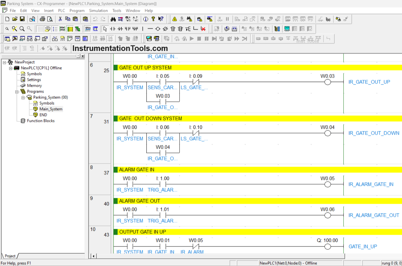
RUNG 7 (GATE OUT DOWN SYSTEM)
Rung 7 has a function to close/lower “Gate OUT”. When the IR_SYSTEM (W0.00) and SENS_CAR_OUT2 (0.06) are Active, then the IR_GATE_OUT_DOWN (W0.04) coil will be Active.
Coil IR_GATE_OUT_DOWN (W0.04) will be disabled when contact LS_GATE_OUT_DOWN (0.10) is ON. Coil IR_GATE_OUT_DOWN (W0.04) has an Interlock function so that if Input SENS_CAR_OUT2 (0.06) is deactivated Coil IR_GATE_OUT_DOWN (W0.04) is still Active.
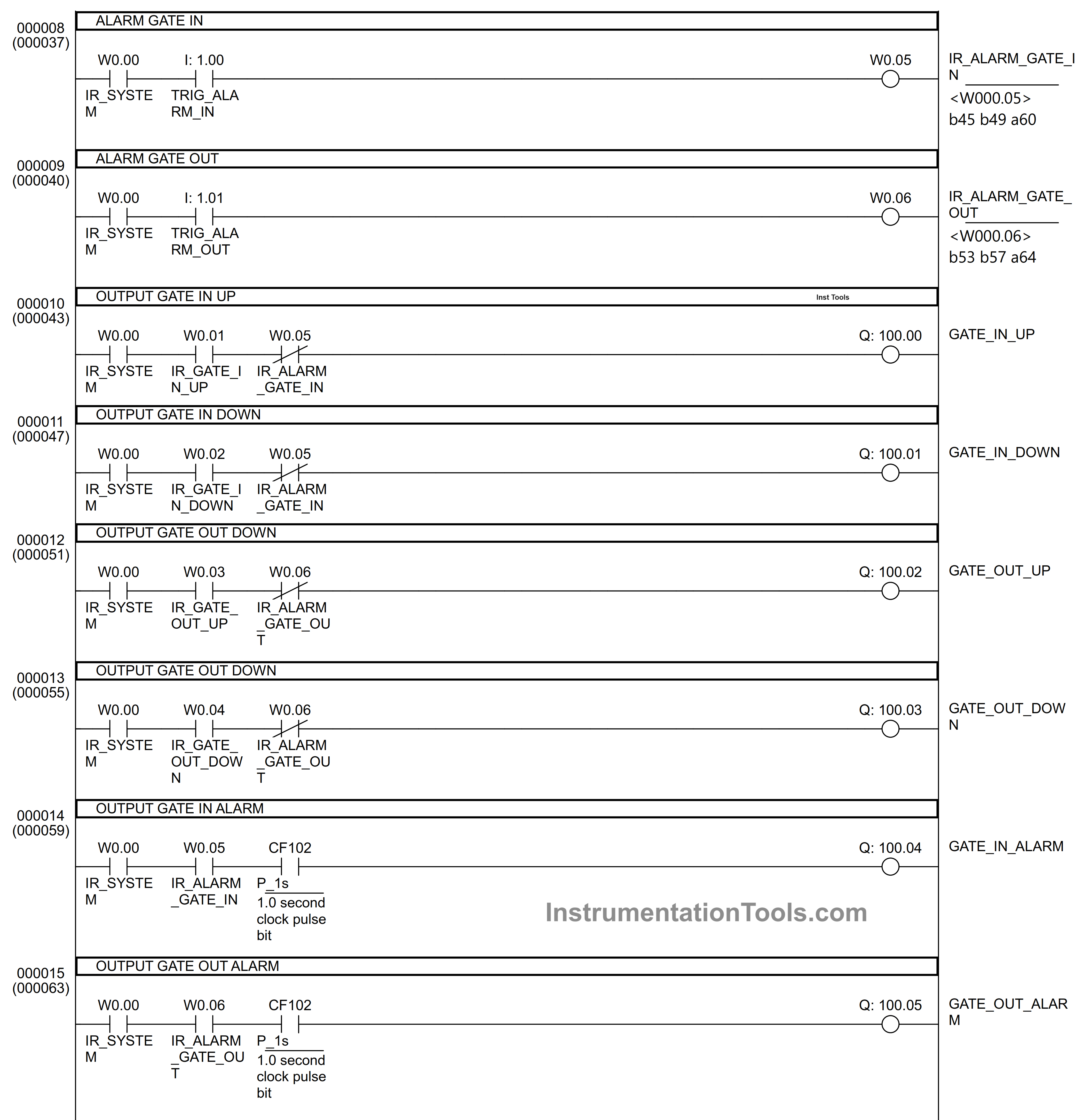
RUNG 8 (ALARM GATE IN)
This Rung functions to Activate the Alarm from “Gate IN”. When the IR_SYSTEM (W0.00) and the TRIG_ALARM_IN (1.00) are Active, then the IR_ALARM_GATE_IN (W0.05) Coil will be Active.
RUNG 9 (ALARM GATE OUT)
This Rung functions to Activate the Alarm from “Gate OUT”. When the IR_SYSTEM (W0.00) and the TRIG_ALARM_OUT (1.01) are Active, then the IR_ALARM_GATE_OUT Coil (W0.06) will be Active.
RUNG 10 (OUTPUT GATE IN UP)
This Rung functions to Activate the Output contact GATE_IN_UP (100.00). When the IR_SYSTEM (W0.00) and the IR_GATE_IN_UP (W0.01) are Active, then the GATE_IN_UP output contact (100.00) will be Active.
The GATE_IN_UP (100.00) output will only be disabled when the IR_ALARM_GATE_IN (W0.05) is ON and when the IR_SYSTEM (W0.00) is OFF.
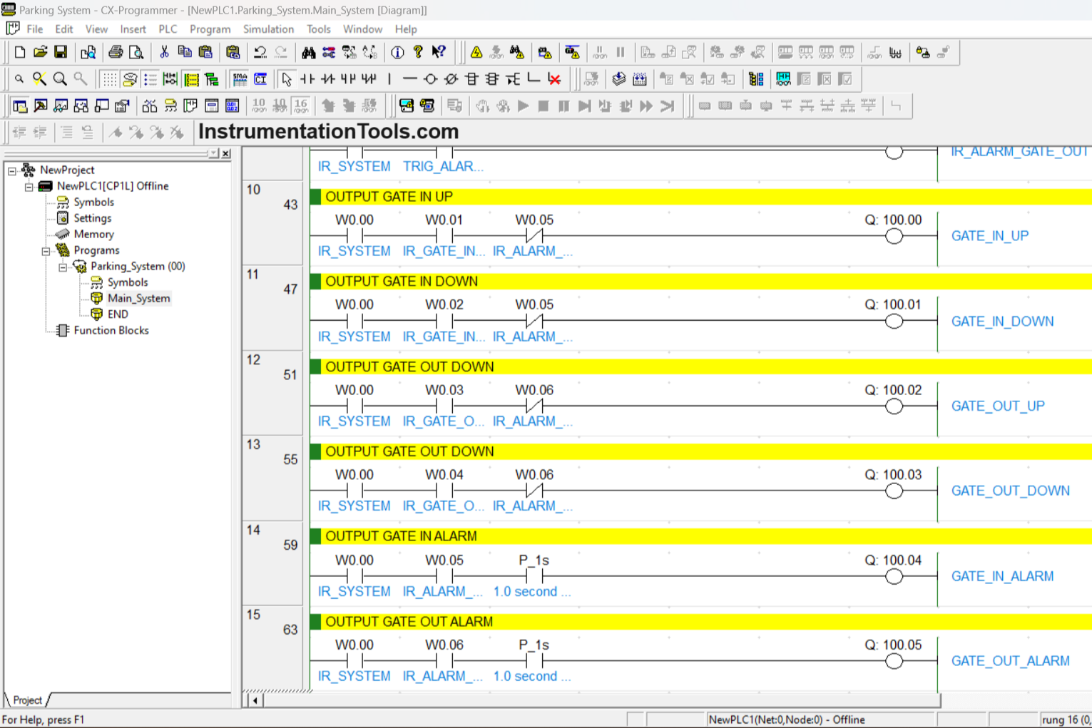
RUNG 11 (OUTPUT GATE IN DOWN)
This rung functions to activate the Output GATE_IN_DOWN (100.01). When the IR_SYSTEM (W0.00) and the IR_GATE_IN_DOWN (W0.02) are active, then the Output GATE_IN_DOWN contact (100.01) will be activated. The Output GATE_IN_DOWN (100.01) will only be deactivated when the IR_ALARM_GATE_IN (W0.05) is active and the IR_SYSTEM (W0.00) is inactive.
RUNG 12 (OUTPUT GATE OUT UP)
This Rung functions to Activate the GATE_IN_DOWN (100.01) Output. When the IR_SYSTEM (W0.00) and the IR_GATE_IN_DOWN (W0.02) are Active, then the GATE_IN_DOWN output (100.01) will be Active. The GATE_IN_DOWN (100.01) output will only be disabled when the IR_ALARM_GATE_IN (W0.05) is ON and when the IR_SYSTEM (W0.00) is OFF.
RUNG 13 (OUTPUT GATE OUT DOWN)
This Rung functions to Activate the Output GATE_OUT_DOWN (100.03). When the IR_SYSTEM (W0.00) and the IR_GATE_OUT_DOWN (W0.04) are Active, the Output GATE_OUT_DOWN (100.03) will be Active. The GATE_OUT_DOWN (100.03) output will only be disabled when the IR_ALARM_GATE_OUT (W0.06) is ON and when the IR_SYSTEM (W0.00) is OFF.
RUNG 14 (OUTPUT GATE IN ALARM)
This Rung functions to Activate the GATE_IN_ALARM (100.04) Output. When the IR_SYSTEM (W0.00) and IR_ALARM_GATE_OUT (W0.05) are Active, the GATE_IN_ALARM (100.04) Output will be Active. Contact NO” P_1s ” functions so that the GATE_IN_ALARM (100.04) Output is Active by blinking every 1 second.
RUNG 15 (OUTPUT GATE OUT ALARM)
This Rung functions to Activate the GATE_OUT_ALARM (100.05) Output. When IR_SYSTEM (W0.00) and IR_ALARM_GATE_OUT (W0.06) are Active then the Output GATE_OUT_ALARM (100.05) will be Active. Contact NO” P_1s ” functions so that the GATE_IN_ALARM (100.04) Output contact is Active by blinking every 1 second.
If you liked this article, please subscribe to our YouTube Channel for PLC and SCADA video tutorials.
You can also follow us on Facebook and Twitter to receive daily updates.
Read Next:
- Automated Garage Gate Control PLC Logic
- Doll Claw Machine using Omron PLC Program
- PLC Program for Ceramic Oven Conveyor System
- PLC Controlling a Water Pump with 3 Power Sources
- Scheduled Daily Plant Watering PLC Programming


good platform for automation engineer i always like this platform
thanks sir