By using this site, you agree to the Privacy Policy and Terms of Use.
Accept
Inst ToolsInst ToolsInst Tools
  • Ask
  • Courses
  • Videos
  • Q & A
    • Interview
      • Instrumentation
      • Electronics
      • Electrical
      • Practical Questions
    • MCQ
      • Instrumentation MCQ
      • Electrical MCQ
      • Electronics MCQ
      • Control Systems MCQ
      • Analog Electronics MCQ
      • Digital Electronics MCQ
      • Power Electronics MCQ
      • Microprocessor MCQ
      • Multiple Choice Questions
  • EE
    • Electronics
      • Electronics Q & A
      • Electronic Basics
      • Electronic Devices & Circuits
      • Electronics Animation
      • Digital Electronics
    • Electrical
      • Electrical Basics
      • Electrical Q & A
      • Power Electronics
      • Electrical Machines
      • Electrical Animation
      • Power Systems
      • Switchgear & Protection
      • Transmission & Distribution
  • Measure
    • Control Valves
    • Calibration
    • Temperature
    • Pressure
    • Flow
    • Level
    • Analyzers
    • Switches
    • Vibration
    • Solenoid Valve
  • Control
    • PLC Tutorials
    • Control Systems
    • Safety Instrumented System (SIS)
    • Communication
    • Fire & Gas System
  • More
    • Design
    • Tools
    • Animation
    • Basics
    • Formulas
    • Standards
    • TextBooks
    • Common
    • Software
    • Excel Tools
    • Erection & Commissioning
    • Process Fundamentals
    • Videos
    • Books
Search
All rights reserved. Reproduction in whole or in part without written permission is prohibited.
Reading: Non-contact Temperature Sensors
Share
Notification Show More
Font ResizerAa
Inst ToolsInst Tools
Font ResizerAa
  • Ask
  • Courses
  • Videos
  • Q & A
  • EE
  • Measure
  • Control
  • More
Search
  • Ask
  • Courses
  • Videos
  • Q & A
    • Interview
    • MCQ
  • EE
    • Electronics
    • Electrical
  • Measure
    • Control Valves
    • Calibration
    • Temperature
    • Pressure
    • Flow
    • Level
    • Analyzers
    • Switches
    • Vibration
    • Solenoid Valve
  • Control
    • PLC Tutorials
    • Control Systems
    • Safety Instrumented System (SIS)
    • Communication
    • Fire & Gas System
  • More
    • Design
    • Tools
    • Animation
    • Basics
    • Formulas
    • Standards
    • TextBooks
    • Common
    • Software
    • Excel Tools
    • Erection & Commissioning
    • Process Fundamentals
    • Videos
    • Books
Follow US
All rights reserved. Reproduction in whole or in part without written permission is prohibited.
Inst Tools > Blog > Temperature Measurement > Non-contact Temperature Sensors
Temperature Measurement

Non-contact Temperature Sensors

Editorial Staff
Last updated: October 30, 2018 7:18 am
Editorial Staff
Share
6 Min Read
SHARE

Virtually any mass above absolute zero temperature emits electromagnetic radiation (photons, or light) as a function of that temperature. This basic fact makes possible the measurement of temperature by analyzing the light emitted by an object. The Stefan-Boltzmann Law of radiated energy quantifies this fact, declaring that the rate of heat lost by radiant emission from a hot object is proportional to the fourth power of the absolute temperature:

Non-contact Temperature Sensors formula

Where,

dQ/dt = Radiant heat loss rate (watts)
e = Emissivity factor (unitless)
σ = Stefan-Boltzmann constant (5.67 × 10⁻⁸ W/m2·K4)
A = Surface area (square meters)
T = Absolute temperature (Kelvin)

The primary advantage of non-contact thermometry (or pyrometry as high-temperature measurement is often referred) is rather obvious: with no need to place a sensor in direct contact with the process, a wide variety of temperature measurements may be made that are either impractical or impossible to make using any other technology.

A major disadvantage of non-contact thermometry is that it only reveals the surface temperature of an object. Sensing the thermal radiation emanated from a pipe, for instance, only tells you the surface temperature of that pipe and not the true temperature of the fluid within the pipe. Another example is when doctors use non-contact thermometry to assess irregularities in body temperature: what they detect is just skin temperature. While it may be true that “hot spots” beneath the surface of an object may be detectable this way, it is only because the surface temperature of that object differs as a consequence of the hot spot(s) beneath. If a hotter-than-normal region inside of an object fails to transfer enough thermal energy to the surface to manifest as a hotter surface temperature, that region will be invisible to non-contact thermometry.

It may surprise some readers to discover that non-contact pyrometry is nearly as old as thermocouple technology, the first non-contact pyrometer being constructed in 1892.

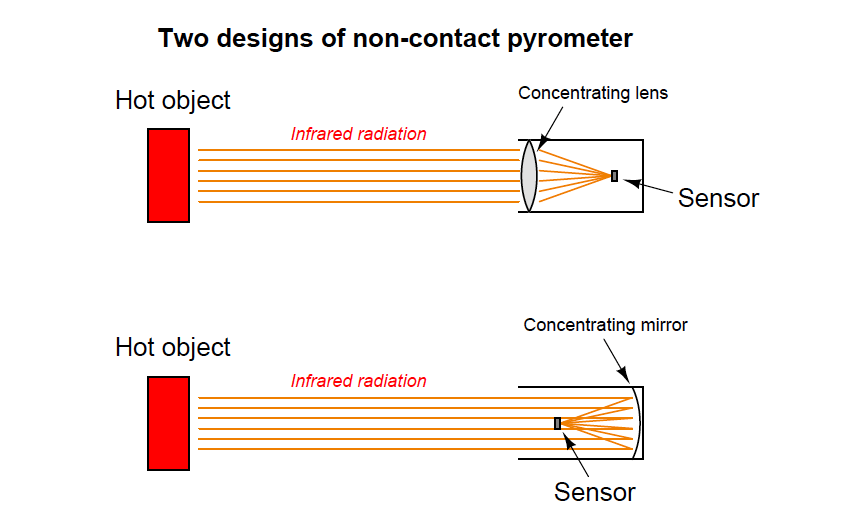
Concentrating Pyrometers

A time-honored design for non-contact pyrometers is to concentrate incident light from the surface of a heated object onto a small temperature-sensing element. A rise in temperature at the sensor reveals the intensity of the infrared optical energy falling upon it, which as discussed previously is a function of the target object’s surface temperature (absolute temperature to the fourth power):

non-contact pyrometer principle

The fourth-power characteristic of Stefan-Boltzmann’s law means that a doubling of absolute temperature at the hot object results in sixteen times as much radiant energy falling on the sensor, and therefore a sixteen-fold increase in the sensor’s temperature rise over ambient. A tripling of target temperature (absolute) yields eighty one times as much radiant energy, and therefore an 81- fold increase in sensor temperature rise. This extreme nonlinearity limits the practical application of non-contact pyrometry to relatively narrow ranges of target temperature wherever good accuracy is required.

Thermocouples were the first type of sensor used in non-contact pyrometers, and they still find application in modern versions of the same technology. Since the sensor does not become nearly as hot as the target object, the output of any single thermocouple junction at the sensor area will be quite small. For this reason, instrument manufacturers often employ a series-connected array of thermocouples called a thermopile to generate a stronger electrical signal.

The basic concept of a thermopile is to connect multiple thermocouple junctions in series so their voltages will add:

multiple thermocouple in series

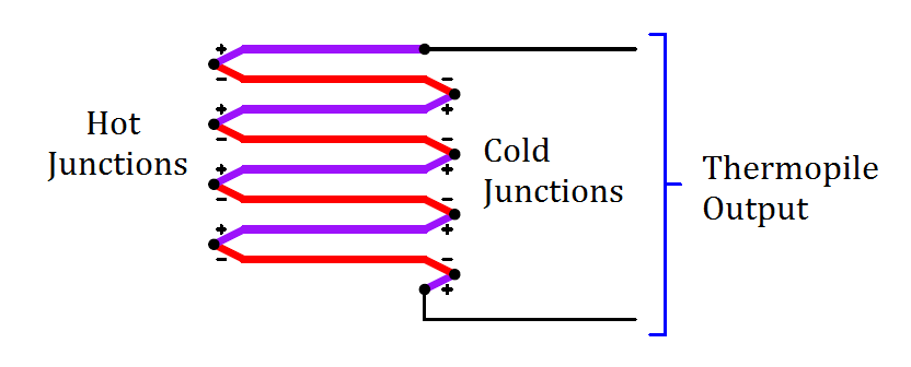
Examining the polarity marks of each junction (type E thermocouple wires are assumed in this example: chromel and constantan), we see that all the “hot” junctions’ voltages aid each other, as do all the “cold” junctions’ voltages. Like all thermocouple circuits, though, the each “cold” junction voltage opposes each the “hot” junction voltage. The example thermopile shown in this diagram, with four hot junctions and four cold junctions, will generate four times the potential difference that a single type E thermocouple hot/cold junction pair would generate, assuming all the hot junctions are at the same temperature and all the cold junctions are at the same temperature.

When used as the detector for a non-contact pyrometer, the thermopile is oriented so all the concentrated light falls on the hot junctions (the “focal point” where the light focuses to a small spot), while the cold junctions face away from the focal point to a region of ambient temperature. Thus, the thermopile acts like a multiplied thermocouple, generating more voltage than a single thermocouple junction could under the same temperature conditions.

Don't Miss Our Updates
Be the first to get exclusive content straight to your email.
We promise not to spam you. You can unsubscribe at any time.
Invalid email address
You've successfully subscribed !
Free Download Thermocouple Calculator
Types of Thermowells
Basics of Temperature Switch
Resistance Temperature Detectors (RTD) Sources of Error
RTD Calculator : Calculate Resistance from Temperature
Share This Article
Facebook Whatsapp Whatsapp LinkedIn Copy Link
Share
Leave a Comment Leave a Comment

Leave a Reply Cancel reply

Your email address will not be published. Required fields are marked *

Stay Connected

128.3kFollowersLike
69.1kFollowersFollow
206kSubscribersSubscribe
38kFollowersFollow

Latest

Top Non-PLC Certification Courses for Automation Professionals
Common
Things You Need to Know About DeviceNet
Communication
Why is IEC 60269 Important
Why is IEC 60269 Important? – Electrical Applications
Standards
NAMUR OPEN ARCHITECTURE
What is NAMUR OPEN ARCHITECTURE?
Control Systems

You Might also Like

Three Wire RTD Wheatstone bridge Circuit
Temperature Measurement

RTD Wheatstone Bridge Circuits

Editorial Staff
Editorial Staff
August 3, 2016
Functions of Temperature Detectors
Temperature Measurement

Functions of Temperature Detectors

Editorial Staff
Editorial Staff
May 23, 2018
Disadvantages of Resistance Temperature Detectors (RTD)
Temperature Measurement

Disadvantages of Resistance Temperature Detectors

Editorial Staff
Editorial Staff
April 14, 2019
Effect of Lead Wire Resistance on RTD
Temperature Measurement

Effect of Lead Wire Resistance on RTD

Editorial Staff
Editorial Staff
October 4, 2016
Burnout Function in Temperature Transmitter
Temperature Measurement

Burnout Function in Temperature Transmitter

vicky
vicky
April 13, 2022
grounded thermocouple junction
Temperature Measurement

Types of Thermocouple Measuring Junction

Editorial Staff
Editorial Staff
November 11, 2017
//

Inst Tools

Sign Up for Our Newsletter

Subscribe to our newsletter to get our newest articles instantly!

[mc4wp_form id=”847″]

Follow US
All rights reserved. Reproduction in whole or in part without written permission is prohibited.
Welcome Back!

Sign in to your account

Username or Email Address
Password

Lost your password?