Inst ToolsInst ToolsInst Tools
  • Courses
  • Automation
    • PLC
    • Control System
    • Safety System
    • Communication
    • Fire & Gas System
  • Instrumentation
    • Design
    • Pressure
    • Temperature
    • Flow
    • Level
    • Vibration
    • Analyzer
    • Control Valve
    • Switch
    • Calibration
    • Erection & Commissioning
  • Interview
    • Instrumentation
    • Electrical
    • Electronics
    • Practical
  • Q&A
    • Instrumentation
    • Control System
    • Electrical
    • Electronics
    • Analog Electronics
    • Digital Electronics
    • Power Electronics
    • Microprocessor
  • Request
Search
  • Books
  • Software
  • Projects
  • Process
  • Tools
  • Basics
  • Formula
  • Power Plant
  • Root Cause Analysis
  • Electrical Basics
  • Animation
  • Standards
  • 4-20 mA Course
  • Siemens PLC Course
Reading: Multiple Pumps Control using PLC
Share
Font ResizerAa
Inst ToolsInst Tools
Font ResizerAa
  • Courses
  • Design
  • PLC
  • Interview
  • Control System
Search
  • Courses
  • Automation
    • PLC
    • Control System
    • Safety System
    • Communication
    • Fire & Gas System
  • Instrumentation
    • Design
    • Pressure
    • Temperature
    • Flow
    • Level
    • Vibration
    • Analyzer
    • Control Valve
    • Switch
    • Calibration
    • Erection & Commissioning
  • Interview
    • Instrumentation
    • Electrical
    • Electronics
    • Practical
  • Q&A
    • Instrumentation
    • Control System
    • Electrical
    • Electronics
    • Analog Electronics
    • Digital Electronics
    • Power Electronics
    • Microprocessor
  • Request
Follow US
All rights reserved. Reproduction in whole or in part without written permission is prohibited.
Inst Tools > Blog > PLC Tutorials > Multiple Pumps Control using PLC

Multiple Pumps Control using PLC

Last updated: March 4, 2021 2:17 pm
Editorial Staff
PLC Tutorials
No Comments
Share
3 Min Read
SHARE

Write the PLC program to control multiple pumps using programmable logic controllers. We have two input pumps used to fill a tank. Make sure pumps operate in an equal amount of time over their lifetime.

Contents
Multiple Pumps Control using PLCProgram Logic:Program Description:Conclusion:

Multiple Pumps Control using PLC

Multiple Pumps Control using PLC

Program Logic:

Develop ladder logic program according to the logic given below,

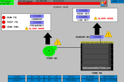
  1. The start/stop push button is provided for control of the two input pump motors P1 and P2.
  2. The Start/Stop pushbutton station is operated to control pump P1.
  3. When the tank is full drain pump motor P3 is started automatically and runs until the low-level sensor is actuated.
  4. After 3 fillings of the tank by pump P1 control automatically shifts to pump P2.
  5. The operation of the start/stop pushbutton now controls pump P2.
  6. After 3 fillings of the tank by pump P2, the sequence is repeated.

PLC Program:

PLC based Multi-Pump Logic
Pump Control with a PLC

Program Description:

Rung 0000:

Start/Stop PB latched with memory B3:0/0.

Rung 0001:

B3:0/0 enabled to turn on B3:0/1 which is to turn ON PUMP P1 (O:0/0) when low-level sensor(I:0/3) turn ON and High-level sensor (I:0/2) is in off condition.B3:0/1 is latched with low-level sensor because pump p1 should not go off once water started rising.

Rung 0002:

Memory contacts used to turn on PUMP P1 (O: 0/0) with counter (C5:0).

Since we are going to shift pump operation from P1 to P2, two counters are used to shift between Pl and P2.

Counter C5:1 is used to turn on PUMP P2(O:0/2).

Rung 0003 & 0004:

B3:0/0 enabled to turn on B3:0/2 which is to turn on PUMP P3(O:0/1) when high-level sensor(I:0/2) turn ON and low-level sensor (I:0/3) is in off condition.B3:0/2 is latched with high-level sensor because pump p3 should not go off once water started reducing.

Rung 0005:

When Pump 3 (O: 0/1) is running, the low-level sensor turns on will make Pump p3 off and pump P1(O:0/0) ON.

Rung 0006:

Both Counter reset is done once the second counter (C5:1) done bit turns ON.

Conclusion:

We can use this example to understand the programming logic in AB PLC.

Author: Hema Sundaresan

If you liked this article, then please subscribe to our YouTube Channel for PLC and SCADA video tutorials.

You can also follow us on Facebook and Twitter to receive daily updates.

Read Next:

  • PLC Example with Timers
  • Traffic Light Control using PLC
  • One-Shot Rising Instruction in PLC
  • Count Running Hours of Pumps
  • Communication between PLC & Energy Meter
Don't Miss Our Updates
Be the first to get exclusive content straight to your email.
We promise not to spam you. You can unsubscribe at any time.
Invalid email address
You've successfully subscribed !

Continue Reading

How to Train Your Maintenance Team for Industrial Automation Systems?
Basic PLC Exercise on Heater and Cooler for Students
How to Create Templates in FactoryTalk View Studio?
PLC Timers Program
PLC Analog Input Card Resolution Effects on Accuracy
PLC FBD Example for Tank Liquid Heating Control by Steam Flow
Share This Article
Facebook Whatsapp Whatsapp LinkedIn Copy Link
Share
Leave a Comment

Leave a Reply Cancel reply

Your email address will not be published. Required fields are marked *

Stay Connected

128.3kFollowersLike
69.1kFollowersFollow
210kSubscribersSubscribe
38kFollowersFollow

Categories

Explore More

Exhaust Fan Control: Example of PLC Timer Programming
Architecture of Allen Bradley PLC
PLC Problems Troubleshooting
Why Use a Current Loop?
What is a Wet Contact? – Basics of PLC Wiring
Grounding or Earthing Scheme in DCS or PLC Systems
Allen Bradley PLC ControlLogix Hardware
MOVE Instruction in PLC – What You Need to Know?

Keep Learning

V1000 Family Programming Simulator Tool

VFD Simulator Download – Free Yaskawa V1000 Software

Address Overlapping in Tia Portal

How to Check Address Overlapping in Tia Portal?

The STAR-DELTA Auto And Manual Program

STAR-DELTA Auto And Manual Program using XG5000 Software

Configuration of Siemens VFD Using TIA Portal

Configuration of Siemens VFD Using TIA Portal Start drive

HMI Screen Design for Hazardous Applications

HMI Screen Design for Hazardous Applications

PLC or DCS Control System Spares

PLC or DCS Control System Spares

PLC Ladder Logic for Motor Control

PLC Program for Motor Starter

What is Process Control ?

What is Process Control?

Learn More

Nuclear Magnetic Resonance Spectrometer Questions and Answers

Nuclear Magnetic Resonance Spectrometer Questions & Answers

Electrical Motor Failures

Most General Reasons for the Electrical Motor Failures

Types of Interrupts Organization Blocks in Tia Portal

Types of Interrupt OB in Siemens Tia Portal

Best Instrumentation Engineering Books to Purchase

Best Instrumentation Engineering Books to Purchase

Digital Electronics Multiple Choice Questions

Memory Devices Objective Questions – Part 5

Control Valve flow coefficient (Cv)

Why we Measure Control Valve flow coefficient (Cv)?

Cybersecurity Projects for Engineering Students

Cybersecurity Projects for Engineering Students

Foxboro pneumatic instruments

Pneumatic Force Balance Instrument

Menu

  • About
  • Privacy Policy
  • Copyright

Quick Links

  • Learn PLC
  • Helping Hand
  • Part Time Job

YouTube Subscribe

Follow US
All rights reserved. Reproduction in whole or in part without written permission is prohibited.
Welcome Back!

Sign in to your account

Username or Email Address
Password

Lost your password?