In the previous article, we talked about how to set up a connection between two PLCs using open user communication, and we used the TCP protocol to connect between two PLCs. We showed in the article how to use instructions like TCON and TDISCON to establish this connection.
In this article, we will show how we can start moving DATA between the PLCs we connected last article. We will use the TSEND and TRCV blocks for this purpose.
We will build on the project we created in the last article, which means there are already the TCON and TDISCON blocks installed into our project. and we will continue our project by adding the TSEND and TRCV blocks to start moving data between the two PLCs.
To send data from PLC_1 into PLC_2 let’s start by creating a data block that will hold all information we need to send to PLC_2. See picture 1.
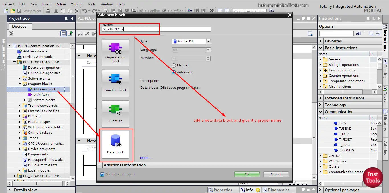
picture 1. Create a new data block.
As we discussed before, it is a better practice to give a proper naming to your blocks, that way it will be easy and intuitive to figure out what is each block are meant for.
Second, let’s add some data inside the Data block which we want to send to PLC_2.
We assumed that we need to send three different data tags. See picture 2.
picture 2. Define some data to send to PLC_2.
There is one more thing we need to do to be able to send the data block we just created to PLC_2 and that is to make sure the optimized block access of the Data block is not selected.
To do that we need to go to properties of the data block and unselect that option. See pictures 3 and 4.
picture 3. Go to properties of data block.
picture 4. Uncheck the Optimized block access option.
Make sure to uncheck this option before using the TSEND block, or it won’t work.
Now that we prepared the data we want to send to the PLC_2 let’s actually attempt to send it. We will do that by using the TSEND block. Just drag and drop the instruction into your main OB1 to add it to your logic. See picture 5.
picture 5. Add TSEND block.
When adding the TSEND block you will be asked to create an instance data block because it is essentially a function block, again give it a proper name. See picture 6.
Picture 6. Create data instance for the TSEND.
When the TSEND block is added into your logic, you will find that there are some important configurations we need to make. See picture 7.
picture 7. The TSEND block.
As you can see, we need to make some configuration:
As for the REQ signal, we will define a tag SendData that will be used to enable the sending of the data.
In the last article, we defined the ID 1 for the connection between PLC_1 and PLC_2, so we will set the ID to 1.
picture 8. Configure the TSEND block.
After we setup the TSEND for sending the data to PLC_2, we need to receive these data inside the PLC_2. To do that we will use the TRCV block. See picture 9.
picture 9. Add TRCV block.
As you can see, just drag and drop the TRCV block to add it into your logic. And you know that next we will need to create a data instance to that block. See picture 10.
picture 10. Add data instance to TRCV block.
After the TRCV block is called into your logic, we will need to configure some parameters as we did with the TSEND. See picture 11.
picture 11. The TRCV block.
As you can see, the EN-R is an enable signal that must be true to allow the TRCV block to start receiving the data. The ID is the connection that will be used and the DATA is where the received data will be stored.
So, we need to create a data block to receive the data inside it. Remember to give it a proper name. See picture 12.
picture 12. Create data block to receive data.
Next, define the information tags that will be received from PLC_1, it is a best practice to ensure the data block hold the same data structure as the data that will be received. See picture 13.
picture 13. Define data tags.
For the EN-R, we will define a RecieveData tag to enable the data receive. And for the connection ID it is 1 as we set it up before. See picture 14.
picture 14. EN-R signal.
Next, drag and drop the data block we created into our TRCV block to finish all configurations. See picture 15.
picture 15. Add your data block into TRCV block.
When you drag and drop the DB we created, you will notice that TIA Portal is giving a warning and that it is not accepting the data block we just added.
And that is because we didn’t unchecked the “Optimized block access” of the data block as we did with TSEND. See picture 16.
picture 16. Optimized block access.
As we said before, we have to uncheck this option otherwise the TSEND and TRCV won’t work. See picture 17.
picture 17. Uncheck the optimized block access option.
You can see that once we unchecked the “optimized block access” the data block is now accepted with the TRCV instruction.
Now that the calling and configuration of the TSEND and TRCV blocks is done. Let’s simulate our project and see how the data will be sent and received.
First we will create a simple logic that ensures that there are data values for our defined tags.
We will create a simple logic to automatically create and update the data values so it will be easier to see the data transfer between the two PLCs. See picture 18.
picture 18. Simple logic.
This simple logic will use the clock bit %M50.5 to automatically change the values of the data stored inside SendToPLC_2 data block.
Let’s compile our project and start a simulation. The first thing we will need to do is to establish the connection between the two PLCs using the TCON block we configured last article.
Remember that we will need to enable the connection capability from PLC_2 and establish the connection with PLC_1. See pictures 19, 20 and 21.
picture 19. No connection between PLCs
picture 20. enable the connection.
picture 21. Establish the connection.
Now, that we established the connection between the two PLCs let’s move the data from PLC_1 into PLC_2 as we set it up.
First, make the SendData tag TRUE. See picture 22.
Picture 22. REQ signal is true.
You can see that, even though the SendData is TRUE, there were no data sent from PLC_1 to PLC_2. And that is because the TRCV block is not yet enabled to receive any data. See picture 23.
picture23. EN-R signal is false.
As you can see, because the RecieveData is not yet TRUE, the TRCV block is not enabled to receive any data. Once the EN-R is true the data will be sent from the data block in PLC_1 into the data block of PLC_2. See picture 24.
picture 24. EN-R signal is True.
Once the EN-R is true, you can see that the data is moved from PLC_1 into PLC_2.
If you open the project and simulate it yourself, you will find the data is continuously being updated in PLC_1 and transferred into PLC_2.
And this is how we can establish a communication between two PLCs and use TSEND, TRCV blocks.
In the next article, we will talk about another compact block that can do the same functionality as the TCON, TDISCON and TSEND using one block.
Download the project files.
If you liked this article, then please subscribe to our YouTube Channel for Instrumentation, Electrical, PLC, and SCADA video tutorials.
You can also follow us on Facebook and Twitter to receive daily updates.
Read Next:
In this post, we will learn the basic requirements for a network switch to be…
The PLC panel and MCC panel interface signals are start, stop, run feedback, trip, local…
In this article, we are going to discuss about shutter door control using induction motor…
Electrical Drives control the motion of electric motors. Motion control is required in industrial and…
PLC ladder logic design to control 3 motors with toggle switch and explain the program…
VFD simulator download: Master the online tool from the Yaskawa V1000 & programming software for…


