Inst ToolsInst ToolsInst Tools
  • Courses
  • Automation
    • PLC
    • Control System
    • Safety System
    • Communication
    • Fire & Gas System
  • Instrumentation
    • Design
    • Pressure
    • Temperature
    • Flow
    • Level
    • Vibration
    • Analyzer
    • Control Valve
    • Switch
    • Calibration
    • Erection & Commissioning
  • Interview
    • Instrumentation
    • Electrical
    • Electronics
    • Practical
  • Q&A
    • Instrumentation
    • Control System
    • Electrical
    • Electronics
    • Analog Electronics
    • Digital Electronics
    • Power Electronics
    • Microprocessor
  • Request
Search
  • Books
  • Software
  • Projects
  • Process
  • Tools
  • Basics
  • Formula
  • Power Plant
  • Root Cause Analysis
  • Electrical Basics
  • Animation
  • Standards
  • 4-20 mA Course
  • Siemens PLC Course
Reading: Motor Feedback Fail Logic in PLC
Share
Notification Show More
Font ResizerAa
Inst ToolsInst Tools
Font ResizerAa
  • Courses
  • Design
  • PLC
  • Interview
  • Control System
Search
  • Courses
  • Automation
    • PLC
    • Control System
    • Safety System
    • Communication
    • Fire & Gas System
  • Instrumentation
    • Design
    • Pressure
    • Temperature
    • Flow
    • Level
    • Vibration
    • Analyzer
    • Control Valve
    • Switch
    • Calibration
    • Erection & Commissioning
  • Interview
    • Instrumentation
    • Electrical
    • Electronics
    • Practical
  • Q&A
    • Instrumentation
    • Control System
    • Electrical
    • Electronics
    • Analog Electronics
    • Digital Electronics
    • Power Electronics
    • Microprocessor
  • Request
Follow US
All rights reserved. Reproduction in whole or in part without written permission is prohibited.
Inst Tools > Blog > PLC Tutorials > Motor Feedback Fail Logic in PLC

Motor Feedback Fail Logic in PLC

You will learn the motor feedback fail logic in PLC which initiates an alarm signal if the motor was not started in 5 seconds.

Last updated: December 23, 2022 5:07 pm
Viral Nagda
PLC Tutorials
3 Comments
Share
3 Min Read
SHARE

You will learn the motor feedback fail logic in PLC which initiates an alarm signal if the motor was not started in 5 seconds.

Let us understand the logic written for detecting motor failure and stopping the system.

A start pushbutton is used to start the motor. A stop button is used to stop the motor. After pressing the start pushbutton, the motor will be started but due to any other reasons if the motor was not started in 5 seconds then initiate an alarm.

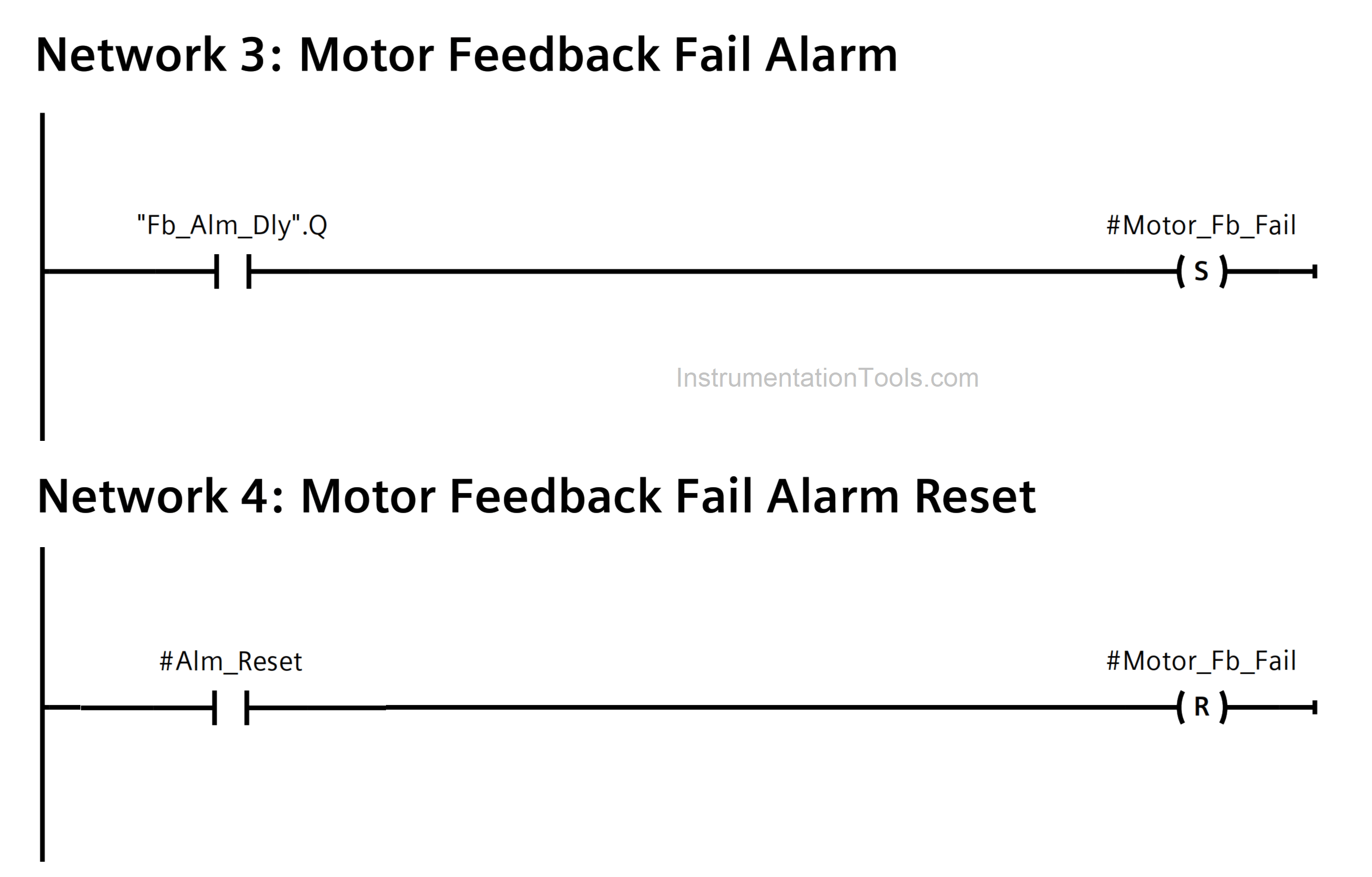
This logic is basically divided into four rungs.

Motor Feedback Fail Logic in PLC
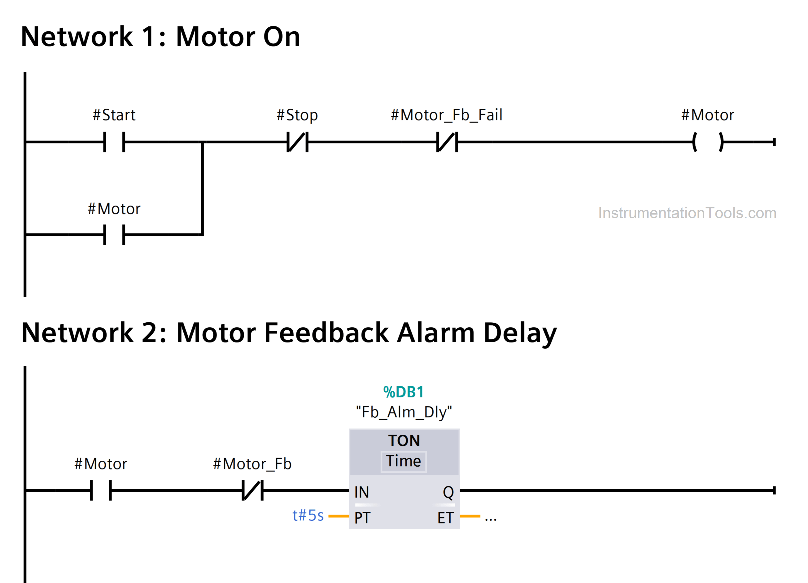
Motor Feedback Fail Logic in PLC
PLC Motor Feedback

Let us understand the flow of each rung one by one:

  1. Start button and stop button are used as PLC inputs. The motor is the digital output. Start button is NO contact and stop button is NC contact. On pressing start button, the motor will start and latch in parallel with start button. This is written in first rung
  2. In the second rung, we check for motor feedback after motor turns ON. If feedback is not received after 5 seconds, then the alarm timer will turn ON.
  3. In the third rung, the alarm timer output turns on the alarm bit and latches it. As soon as this happens, the first rung is cut off due to alarm contact, and the motor turns OFF. Now, the motor will remain OFF as long as the alarm is ON.
  4. In the fourth rung, the alarm reset input is used to reset the alarm. As soon as the alarm is reset, the motor path will again become open for operation in the first rung. Then, after pressing start button, the cycle repeats.

If you liked this article, then please subscribe to our YouTube Channel for Instrumentation, Electrical, PLC, and SCADA video tutorials.

You can also follow us on Facebook and Twitter to receive daily updates.

Read Next:

  • Automation Documents
  • Delta PLC & VFD Modbus
  • Compare PLC and SCADA
  • PLC and DCS System Checks
  • DCS System Maintenance
Don't Miss Our Updates
Be the first to get exclusive content straight to your email.
We promise not to spam you. You can unsubscribe at any time.
Invalid email address
You've successfully subscribed !

Continue Reading

Automatic Packing of Bottles Programming
Animation of Electromagnetic Relay
PLC Program to Read Temperature in PLC
Tia Portal – Optimized and Standard Data Block Access
Difference Between Wifi and Industrial Wireless
Components of PLC
Share This Article
Facebook Whatsapp Whatsapp LinkedIn Copy Link
Share
3 Comments
  • Supriadi says:
    December 25, 2022 at 8:09 pm

    how can the timer work while not getting power supply

    Reply
  • Deen says:
    December 30, 2022 at 9:26 am

    Is #Motor_Fb tag in rung 2 a PLC input?

    Reply
    • Editorial Staff says:
      December 30, 2022 at 2:52 pm

      Yes, motor running feedback from substation/mcc.

      Reply

Leave a Reply Cancel reply

Your email address will not be published. Required fields are marked *

Stay Connected

128.3kFollowersLike
69.1kFollowersFollow
210kSubscribersSubscribe
38kFollowersFollow

Categories

Explore More

Move Instruction in Tia Portal
The Purpose of Marshalling Cabinet or Marshalling Panel
Electrical Cabinet Air Conditioner – Enclosure Cooling, Maintenance
SCADA and HMI Systems – Differences, Similarities, Purpose
PLC Programming for Garden Sprinkler System
Ladder Logic for Stair-Case wiring using Toggle Switches
Introduction to Functional Block Diagram in Studio 5000
PID in Siemens TIA Portal

Keep Learning

Digital Output Card With Relay and Wet Contact

Wiring Diagrams of PLC and DCS Systems – DI, DO, AI, AO

Free Download PLC Simulator using Excel

PLC Simulator using Excel

how-a-plc-do-the-scaling-for-a-sensor

How a PLC do the Scaling for a Sensor ?

Siemens PLC Force LED

Forcing and Modifying PLC Logic

Control Methods in Servo Motor Drives

Various Control Methods in Servo Motor Drives

Communicate with Excel from Intouch SCADA

How to Communicate with Excel from Intouch SCADA?

Simatic 300 Station Configuration

Monitor and Modify Variables in Simatic Manager

Power Supply Sizing for Industrial Automation Systems

Power Supply Sizing for Industrial Automation Systems

Learn More

Feedback Characteristics of Control Systems

Feedback and Non-feedback Systems Objective Questions

PLC Ladder Logic Simulator Mobile Apps For Android

PLC Ladder Logic Simulator Mobile Apps For Android

Flow Measurement Objective Questions

Flow Measurement Objective Questions

Layer-2 and Layer-3 Network Switches

Layer-2 and Layer-3 Network Switches

Two out of Three Logic Analogy

Proximity Switch Working Animation

Proximity Switch Working Animation

safety gas analyzer

Safety Gas Analyzers

Digital Electronics Multiple Choice Questions

K-Map Simplification Objective Questions

Menu

  • About
  • Privacy Policy
  • Copyright

Quick Links

  • Learn PLC
  • Helping Hand
  • Part Time Job

YouTube Subscribe

Follow US
All rights reserved. Reproduction in whole or in part without written permission is prohibited.
Welcome Back!

Sign in to your account

Username or Email Address
Password

Lost your password?