This article will discuss the use of Modbus RTU communication protocol simulator software, namely Modbus Poll and Modbus Slave. Modbus RTU is a variant of the Modbus protocol that uses serial communication (RS-232/RS-485) with binary encoding and follows a master-slave standard. Modbus RTU is widely used in industrial applications to connect devices such as PLCs, sensors, HMIs, and controllers.
Modbus Communication
Modbus uses the Master and Slave concept. Devices designated as Masters can send commands to devices designated as Slaves.
- Master: Initiates communication/Request (e.g., HMI or PC).
- Slave: Responds to requests/Response (e.g., sensors or PLC).
Communication Media
Modbus uses the RS-485 protocol (multi-drop) or RS-232 protocol (point-to-point). Common baud rates: 9600, 19200, 38400, 57600, 115200 bps.
Data Format
Each data byte is sent as 1 full byte (8 bits) + parity (optional). Data is sent in frames (packets) consisting of:
Slave Address: Target device (1…247). Slave devices in Modbus communication are limited to a maximum of 247 devices, each with its own ID address.
Function Code: A command number telling the slave what to do. These are the available Function Codes:
01: Read Coils (read digital outputs).
02: Read Discrete Inputs (read digital inputs).
03: Read Holding Registers (read/write registers).
04: Read Input Registers (read input registers only).
05: Write Single Coil (write 1 digital output).
06: Write Single Register (write 1 holding register).
15/16: Write Multiple Coils/Registers.
Data: Data to be read/written, such as register addresses, register values, etc.
CRC (Cyclic Redundancy Check): 2 bytes for error detection.
Modbus RTU (Serial) Configuration Parameters
Baud Rate: Serial data transfer speed in bits per second (bps), e.g., 9600, 19200, 38400, up to 115200 bps.
Data Bits: Number of actual data bits per character, typically 7 or 8 bits.
Parity: Parity error detection scheme (None, Even, Odd) applied to each byte.
Stop Bits: Additional bits marking the end of a serial data frame, usually 1 or 2 bits.
Slave ID: Numeric slave address (range: 1-247).
Timeout: Maximum duration (in milliseconds) for the master to wait for slave response, e.g., 100-1000 ms.
COM Port: Physical or virtual serial port identification (examples: COM1, COM2) used for communication.
Software Used
In the video below, we show how to use Modbus Poll and Slave software with a detailed simulation.
Modbus Poll
Modbus Poll is a Modbus Master simulator software. This software can be used as a master to send commands and read data from Modbus slave devices.
Modbus Slave
Modbus Slave is a Modbus Slave simulator software. This software can be used as a receiving device for commands from Master devices.
VSPE (Virtual Serial Port Simulator)
VSPE (Virtual Serial Ports Emulator) is software designed to create virtual COM ports without the need for physical hardware ports.
Purpose of the Modbus Simulation
Modbus Poll software can read and send data to the Modbus Slave software with the following parameter configuration:
- Baud Rate: 19200Bps
- Data Bits: 8-bit
- Parity: Even
- Stop Bits: 1
- Slave ID: 1
- Timeout: 200ms
- COM Port: COM10 (virtual)
Modbus Poll and Modbus Slave Simulation
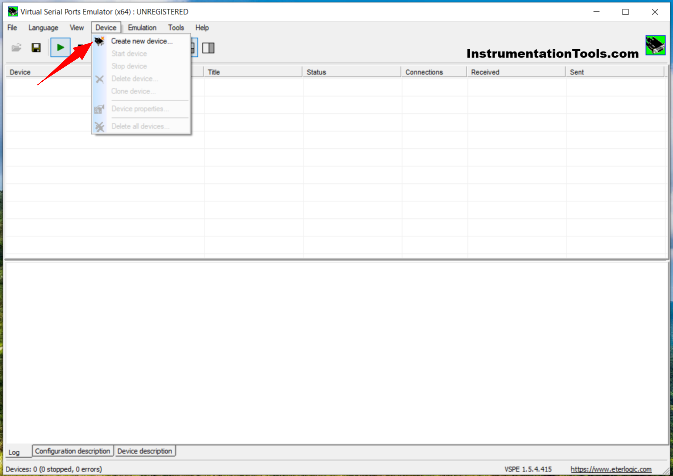
1. Open the VSPE Software. Click “Device” → “Create new device”.
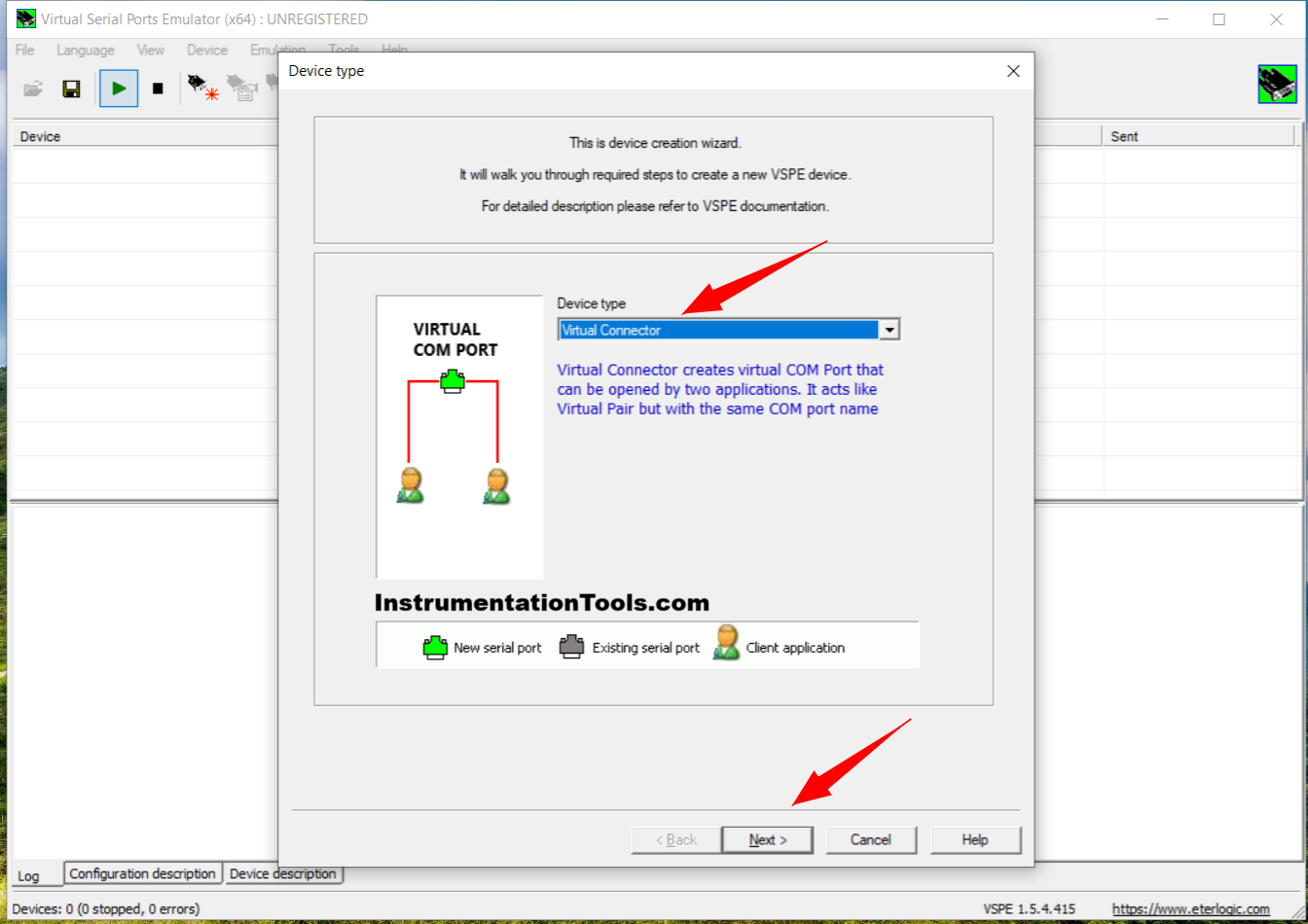
2. Set the Device type to “Virtual Connector” → Click “Next”.
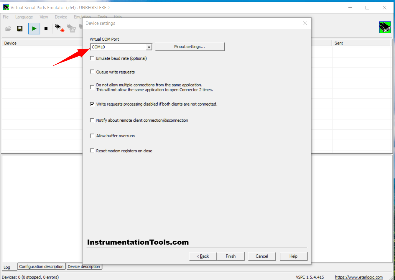
3. Set the Virtual COM Port to “COM 10” → Click “Finish”.
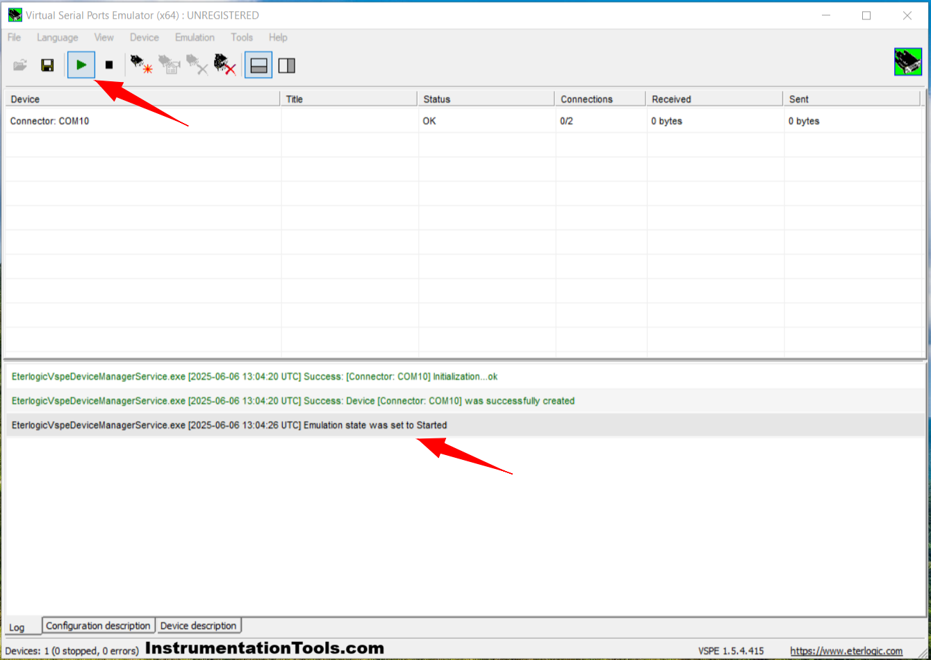
4. Click the “Start Emulation” icon, and check the log for a message indicating that the Emulation process has started.
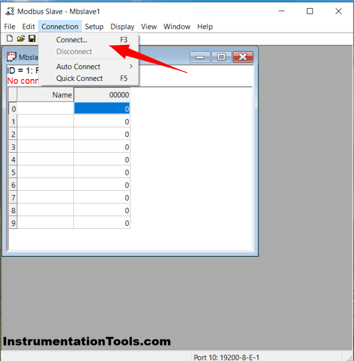
5. Open the Modbus Slave Software. Click “Connection” → Click “Connect”. Or press F3.
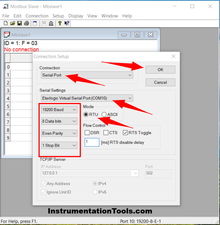
6. Configure the Connection: Serial Port, Serial Setting: COM 10, Baud: 19200, Data Bits: 8, Parity: Even, Stop Bit: 1, and Mode: RTU. Click “OK”.
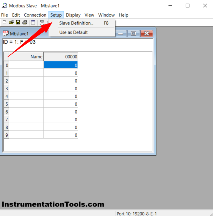
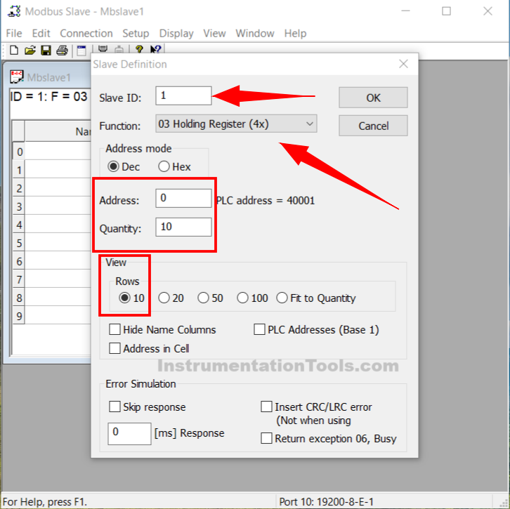
7. Click the “Setup” menu → Click “Slave Definition”. Or press the F8 key.
8. Set Slave ID: 1, Function: 03 Holding Register, Address: 0, Quantity: 10, and Rows: 10. Click “OK”.
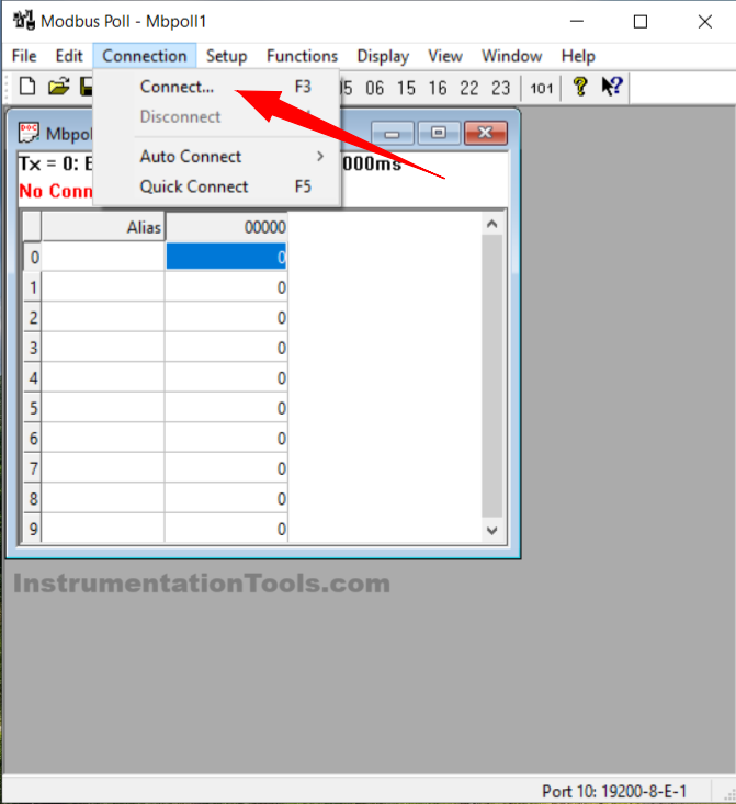
9. Open the Modbus Poll Software. Click “Connection” → Click “Connect”. Or press F3.
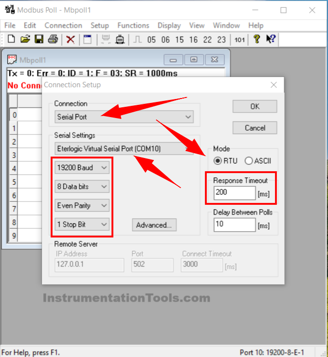
10. Configure the Connection: Serial Port, Serial Setting: COM 10, Baud: 19200, Data Bits: 8, Parity: Even, Stop Bit: 1, Mode: RTU, Response Timeout: 200 ms. Click “OK”.
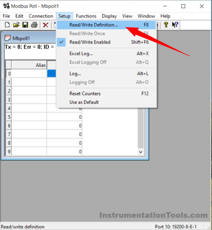
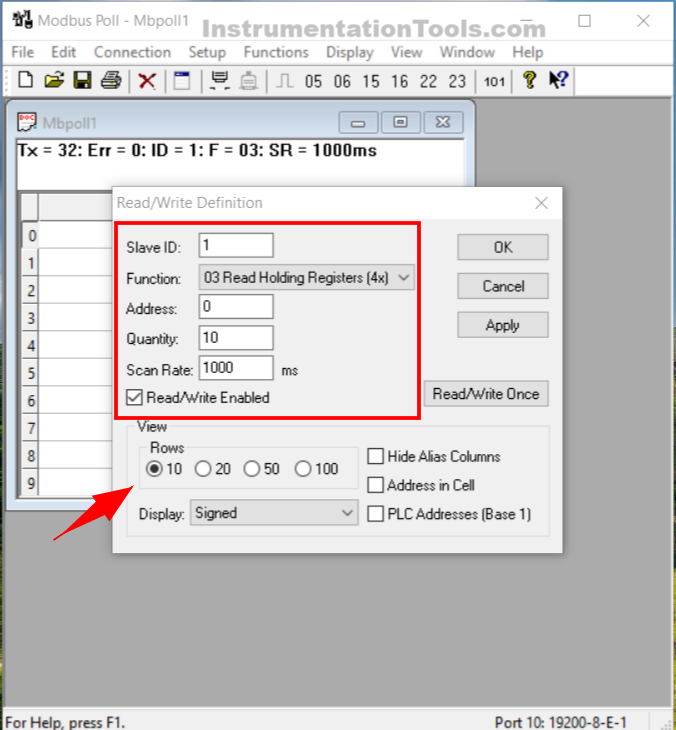
11. Click the “Setup” icon → Select “Read/Write Definition”. Or press the F8 key.
12. Set Slave ID: 1, Function: 03 Holding Register, Address: 0, Quantity: 10, Scan rate: 1000 ms, Rows: 10, and enable the “Read/Write Enabled” function. Click “OK”.
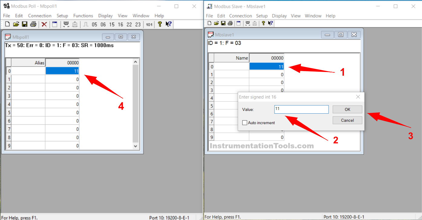
13. To read data from Modbus Slave, input values in the Modbus Slave Address column → Click “OK”. The entered data will automatically be read in Modbus Poll.
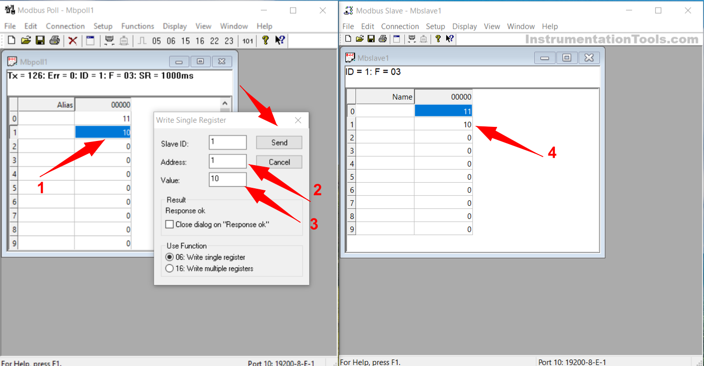
14. To send data from Modbus Poll, input values in the Modbus Poll Address column. Set the value to be sent, Address, and Slave ID → Click “Send”. The entered data will automatically be read in Modbus Poll.
Read Next:
- Free Download & Install Modbus Simulator Software
- How is Modbus used in Industrial Networking?
- PLC Programming for Digital Alarms Configuration
- Vacuum Cleaner PLC Programming Explained
- School Attendance System PLC Programming


Realmente no entiendo nada: ¿Quién lee? ¿Quién escribe? Yo lo que quiero es probar la comunicación de un plc Delta DVP, que supuestamente tengo configurado como maestro, con el software slave. El software usa unas direcciones que no entiendo: 01, 02, 03 y 04. Por otro lado, El plc delta usa registros D con un número consecutivo (0, 1,2,…, 100, 200, etc.).
Ningún video tutorial en YouTube explica bien como configurar los enlaces de cualquier equipo con otro, si se supone que es un protocolo universal. Pareciera que en la práctica el enlace de un plc delta y un sensor de temperatura es algo muy distinto a un variador de frecuencia, por ejemplo. Y si cambias de marca de plc también es otra cosa muy distinta.