Write the PLC program to read the energy meter readings in the programmable logic controller (PLC) using Modbus Communication.
Energy Meter Modbus Communication

Consider Modbus protocol supported energy meter and display the readings in the PLC. In PLC, Modbus instructions are used to read the energy meter parameters.
First, we have to Set communication parameters like address, baud rate, parity, etc. in the energy meter as per requirement or standard data.
For example, consider the energy meter that has the following parameters.
- Address = 2,
- Baud rate = 19200 and
- Parity bit = 0.
We will read frequency data in the PLC from the energy meter using Modbus communication. In energy meter, different parameters are available in the Modbus and each parameter has a unique address (register) where the readings are stored.
As we are planning to get the “frequency” data into the PLC, we need its specific address and assume it as 40106. So we need to use this address in our PLC configuration, DATA_ADDR is 40106 in the MB master block.
Configure pointer address in DATA_PTR so the frequency will be received in PLC address MW500. If floating value needed, use conversion instruction to convert INT value to REAL value.
The same setting should be in PLC for Modbus RTU communication. Set all the above parameters (address, baud rate, and parity) in the MB COMM LOAD block in PLC.
MODBUS MASTER:-
Modbus master instruction is used for data communication in PLC. MB master instruction allows the program to communicate as a Modbus master using the port on a point to point module.
An instant DB will be created when a Modbus master is created in a program.
MB COMM MASTER:-
MB COMM LOAD instruction execution is necessary before using Modbus master instruction. So we used MB COMM LOAD instruction also.
MB COMM LOAD instruction configures a port for communication using the Modbus RTU protocol.
List of Memory bits
MB COMM LOAD memory bits
- M1.2:-Always true
- M1.0:-First scan
- M800.0:-Done bit
- M800.1:-Error bit
- MW802:-Status word
MB_MASTER memory bits
- M1.2:-Always true
- M0.7:-Clock pulse
- M803.0:-MB master done bit
- M803.1:-MB master busy bit
- M803.2:-MB master error bit
- MW804:-MB master status word
- MW500:-Frequency in INT
- MD700:-Frequency in Real.
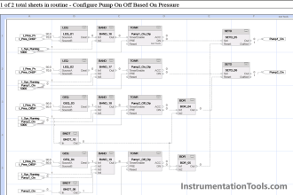
Ladder diagram PLC Modbus communication
Network 1:-
MB COMM LOAD parameters

Network 2:-
MB MASTER Parameters

Network 3:-
INT to REAL conversion instruction.

Program Description
Network 1:-
In this network, we have taken MODBUS COMM LOAD instruction for port communication. In this network, we have configured the port, baud rate and parity for communication.
Network 2:-
In this network, MODBUS_MASTER instruction used will allow the program to communicate as a Modbus master using the port on the module. Here we have configured Modbus data address parameters for the device.
Network 3:-
Conversion instruction is used for data format conversion from INT to REAL.
Done bit:- If false then transaction not completed and true then transaction completed without error
Busy bit:- If false then MB no MB master transaction in process and true then MB master transaction in process.
Error:- If false then no error in the block and true then error in block.
Status word:- Show error code for troubleshooting.
Now we get the data into the PLC registers. So we can use this data in our other function blocks or use them in graphics to display the readings for the operator.
Note:- Above application may be different from the actual application. This example is only for explanation purposes only. We can implement this logic in other PLC also. This is the simple example of meter data reading in PLC using Modbus communication, we can use this concept in other examples also. All parameters and graphical representations considered in this example are for explanation purposes only, parameters or representation may be different in actual applications. Also, all interlocks are not considered in the application.
Author: Bhavesh
If you liked this article, then please subscribe to our YouTube Channel for PLC and SCADA video tutorials.
You can also follow us on Facebook and Twitter to receive daily updates.
Read Next:
Comparison Instructions in PLC
Demultiplexer PLC ladder diagram
Industrial Communication Network
Data Handling Instructions in PLC


Really nice explanation. I wishing best of luck for author.
Thanks. It was great.
I think nothing better could have been than this. You are doing a job that could make duffers like me expert in this field. I must say instrumentationtools.com is no doubt a free lunch.