Mechanical Vibration Switches provide vibration protection for low- to medium-speed machinery. An inertia sensitive mechanism activates a snap-action switch with SPDT output contacts if the vibration exceeds an adjustable setpoint.
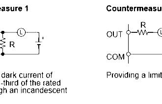
The mechanical vibration switch contacts can be used to activate an alarm or initiate equipment shutdown as per our requirement. Some optional settings also available like Electrical (remote) reset (right side figure) with start-up time delay and a second set of SPDT output contacts to accommodate DPDT needs (e.g. separate trip and trip light circuits) are available.
Mechanical Vibration Switch
Mechanical Vibration Switches offer basic protection against gross changes in structural seismic acceleration.

The operating mechanism is purely mechanical and consists of a tension spring attached to a pivoting plate on an over-center fulcrum – magnets are not employed. Normally, this plate is in an untripped position (Figure A).
However, in the presence of sufficient seismic acceleration (whether vibratory or impact), the trip plate will pivot beyond this over-center position, snapping to a stable tripped position (Figure B) where it contacts an internal micro-switch relay, changing the state of the relay.
This relay is available for external wiring connections where on/off changes in electrical continuity can be used to trip the machine and/or annunciate excessive vibration.

Once the switch has assumed its tripped position, it must be reset manually by means of the external reset plunger (optional), or by means of a remote electrical reset (optional).
The remote reset capability can also be used as a startup delay to hold the switch in an untripped state for as long as coil excitation is supplied – up to 30 seconds (optional feature, the maximum duration is governed by a non-adjustable, factory-installed thermistor circuit). The startup delay feature is useful during machinery startup when vibration in excess of the normal trip setting may be temporarily incurred.
Application
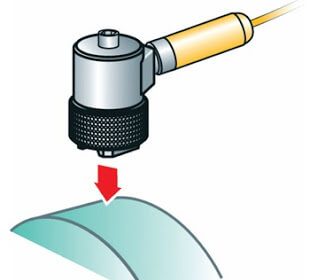
Mechanical vibration switches are typically used on cooling tower fans and mounted such that loss of a blade will result in significant structural acceleration at the switch mounting location (Figure 2).

The switch may be used on other types of machinery as well, but care must be taken to ensure that adequate change in acceleration between “normal” and “malfunction” conditions will exist at the switch’s mounting location.
The switch is not designed to reliably trip for acceleration levels below approximately 1 g (9.8 m/s2 ), or when less than 1 g exists between a machine’s normal running vibration levels and malfunction vibration levels.
Primary Variables Affecting Operation of Vibration Switch
The required seismic acceleration to move the 5550 or 5550G mechanical switch from its untripped position to its tripped position is a function of three variables. They are
Variable #1 – Spring Force Direction
The movable trip plate mass inside the switch housing is free to move on an essentially frictionless pivot, and is restrained in its untripped position by a spring. By turning the setpoint adjustment screw (Figure 3), changes are made to the spring’s direction, and to a much lesser extent, its tension.
Thus, the spring mechanism exerts an essentially constant force on the trip plate and turning the setpoint adjustment screw changes the direction of this force. Turning the setpoint screw clockwise (CW) aligns the spring force more fully in the untripped direction (below the pivot – see Figure 1), making it more difficult to trip the device. Turning the setpoint screw counter-clockwise (CCW) does the opposite, making it easier to trip the device.

Variable #2 – Switch Orientation
Depending on how the switch is oriented, gravity will act on the trip mechanism’s movable mass to either add to or subtract from the spring force. For both model 5550 and 5550G switches, the switch orientation is the direction in which the cover faces.
With the switch oriented horizontally (Figure 4A), the effects of gravity will be negligible and only the spring force will govern the trip plate’s behavior. With the switch oriented vertically up (Figure 4B), gravity acts to keep the trip plate’s movable mass in the untripped position, and inertial excitation must counteract both gravity and the spring force.
With the switch oriented vertically down (Figure 4C), gravity acts in the opposite direction and opposes the spring’s force. Thus, with the same setpoint adjustment, a switch facing up will require the most excitation to trip, a switch facing horizontally will require 1g less excitation to trip, and a switch facing down will require 2g less excitation to trip.

Variable #3 – Vibration Forces Acting on the Switch
By shaking or impacting the switch along its sensitive axis with sufficient inertial force for a sufficient duration and within its frequency response range, the trip plate mechanism will overcome the combined forces of gravity (depending on orientation) and spring tension, snapping from its untripped position to its tripped position.
Maintenance Convenience Versus Measurement Quality
While it is desirable to mount the switch in a location in which it can be easily serviced and maintained, this should not be the dominant consideration.
The switch serves as a mechanical sensor and for it to provide suitable machinery protection, it must be mounted in a location and orientation where the machine’s inertial forces during malfunction conditions will be suitably large to trip the switch.
Thus, locating the switch for optimal mechanical sensing – rather than optimal serviceability – must always remain the primary consideration. However, in most circumstances, judicious choice of mounting location and switch orientation can accommodate both requirements satisfactorily.
a. Sensitive Axis
The switch is designed to respond to inertial forces only in the direction of its sensitive axis (Figure 4). When care is not taken to mount the switch properly, relatively large inertial forces can occur elsewhere on the machine that will not be transmitted properly to the switch, and/or will occur in a direction perpendicular to the switch’s sensitive axis. Both of these conditions can render the switch’s ability to trip less effective or even ineffective.
b. Horizontal Orientation
A horizontal orientation of the switch means that it is mounted with its sensitive axis perpendicular to the direction of gravity (refer to Figure 4A). In this orientation, the effects of gravity on the switch’s trip mechanism are negligible and the trip point is governed almost entirely by the spring.
It is recommended that the switch be oriented horizontally because most machines are less constrained (less stiff) in the horizontal direction than in the vertical direction and will therefore vibrate more in the horizontal direction.
c. Vertical Orientation
A vertical orientation of the switch means that it is mounted with its sensitive axis parallel to the direction of gravity. It is not recommended that the switch be oriented vertically (except as noted above) because most machines are more constrained (more stiff) in the vertical direction than in the horizontal direction, and will therefore vibrate less in the vertical direction.
d. Horizontal Machines
Although Figures 5 and 6 both show horizontal switch orientations, they are not equivalent. In Figure 5, the sensitive axis of the switch points directly at the machine’s shaft; in Figure 6, it does not and instead is aimed at point P somewhere above the shaft. Either mounting orientation can be effective, but 5 is preferred.


Figure 7 shows the same horizontal machine as in Figures 5 and 6, but with the switch oriented vertically. A vertical orientation of the switch is discouraged because machines will generally experience less vibration in the vertical direction than in the horizontal direction, and the switch will be less effective.
Metrix does not recommend installation as shown in Figure 7 unless the machine truly experiences more vibration in the vertical direction than in the horizontal direction, or the 2g / 24V reset coil option is being used.

e. Vertical Machines
Figure 8 shows the preferred installation for a vertical machine. The switch is mounted horizontally and with its sensitive axis pointing directly at the shaft.
In contrast, Figure 7 shows the switch mounted vertically, which is not recommended. Because most vertical machines (like horizontal machines) are rigidly fixed by a baseplate or other mounting that constrains them from vibrating in the vertical direction, aligning the switch’s sensitive axis in the vertical direction aligns it in the direction of least vibration.
Instead, mount the switch as shown in Figure 5 to ensure that radial (not axial) vibration is detected. Mount the switch as shown in Figure 7 only when the machine actually vibrates more in the vertical than horizontal direction, or when the 2 g /24 V reset coil option is used.

Source : metrix vibration