The pattern of bits in the mask determines which bits will be passed from the source address to the destination address, and which bits will be masked. Only bits in the mask that are set (1) will activate the mask operation. In this article, MVM (Masked Move) is discussed.
Masked Move Instruction Block Diagram
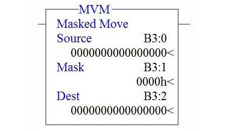
MVM Instruction Description
There are three parameters in MVM,
Source :
It is the address of the data you wants to move.
Mask :
Address of the mask through which the instruction moves data. The mask acts like a filter for the destination.
Destination :
It is the address where the instruction moves the data.
There are three ways to give mask address,
- To enter a hexadecimal mask: type the hexadecimal value followed by the letter H (Hexadecimal).
- To enter a binary mask: type the binary value followed by the letter B (Binary).
- To enter a decimal mask: type the decimal value.
Note : RSLogix will make any necessary conversion and display the hexadecimal value.
MVM Instruction Function :
Activation of mask bit pattern will move the data in Source address to destination address. Move function will not happen until mask bit is activated.
Example 1
When the rung condition goes true,
Case 1
Output When Mask Bit is not activated,
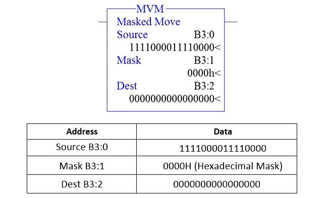
Case 2
Output When Mask Bit is activated,
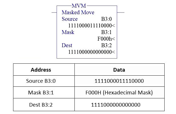
Example 2
When the rung condition goes true,
Case 1
Output When Mask Bit is not activated,
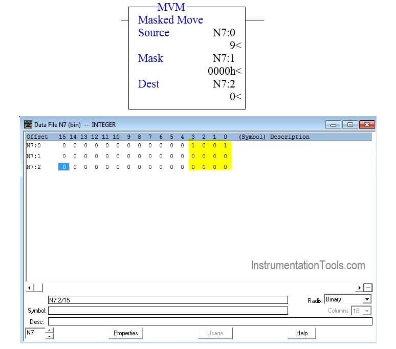
Case 2
Output When Mask Bit is activated,
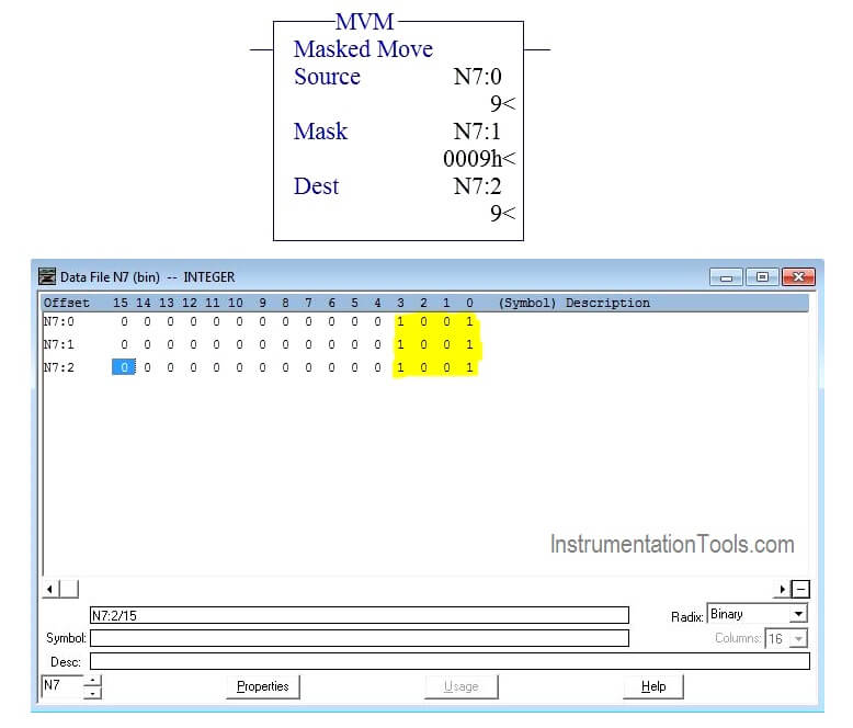
Example PLC Program using MVM Instruction
In this program, When N7:2 equals to the value 9, turn ON O:0/0,
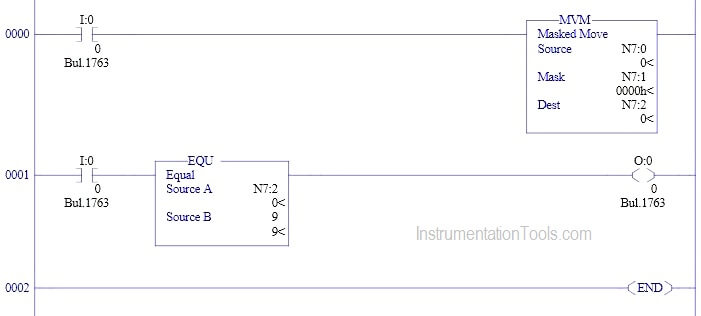
Program Description
Rung 0000
When input condition goes true (I:0/0 turns “ON”),MVM instruction will move the data in N7:0 to N7:2.
Rung 0001
Equal block is used from comparator function to turn on O: 0/0 when N7:2 equal 9.
Conclusion
The above explained concept for Masked Move is for example only. We can use this example program to understand the working of MVM instruction in AB PLC.
If you liked this article, then please subscribe to our YouTube Channel for PLC and SCADA video tutorials.
You can also follow us on Facebook and Twitter to receive daily updates.
Read Next:
