Inst ToolsInst ToolsInst Tools
  • Courses
  • Automation
    • PLC
    • Control System
    • Safety System
    • Communication
    • Fire & Gas System
  • Instrumentation
    • Design
    • Pressure
    • Temperature
    • Flow
    • Level
    • Vibration
    • Analyzer
    • Control Valve
    • Switch
    • Calibration
    • Erection & Commissioning
  • Interview
    • Instrumentation
    • Electrical
    • Electronics
    • Practical
  • Q&A
    • Instrumentation
    • Control System
    • Electrical
    • Electronics
    • Analog Electronics
    • Digital Electronics
    • Power Electronics
    • Microprocessor
  • Request
Search
  • Books
  • Software
  • Projects
  • Process
  • Tools
  • Basics
  • Formula
  • Power Plant
  • Root Cause Analysis
  • Electrical Basics
  • Animation
  • Standards
  • 4-20 mA Course
  • Siemens PLC Course
Reading: How to use Masked Move Instruction in PLC
Share
Notification Show More
Font ResizerAa
Inst ToolsInst Tools
Font ResizerAa
  • Courses
  • Design
  • PLC
  • Interview
  • Control System
Search
  • Courses
  • Automation
    • PLC
    • Control System
    • Safety System
    • Communication
    • Fire & Gas System
  • Instrumentation
    • Design
    • Pressure
    • Temperature
    • Flow
    • Level
    • Vibration
    • Analyzer
    • Control Valve
    • Switch
    • Calibration
    • Erection & Commissioning
  • Interview
    • Instrumentation
    • Electrical
    • Electronics
    • Practical
  • Q&A
    • Instrumentation
    • Control System
    • Electrical
    • Electronics
    • Analog Electronics
    • Digital Electronics
    • Power Electronics
    • Microprocessor
  • Request
Follow US
All rights reserved. Reproduction in whole or in part without written permission is prohibited.
Inst Tools > Blog > PLC Tutorials > How to use Masked Move Instruction in PLC

How to use Masked Move Instruction in PLC

Last updated: January 17, 2022 7:21 pm
Editorial Staff
PLC Tutorials
No Comments
Share
3 Min Read
SHARE

The pattern of bits in the mask determines which bits will be passed from the source address to the destination address, and which bits will be masked. Only bits in the mask that are set (1) will activate the mask operation. In this article, MVM (Masked Move) is discussed.

Contents
Masked Move Instruction Block DiagramMVM Instruction DescriptionMVM Instruction Function :Example 1Example 2Example PLC Program using MVM InstructionProgram DescriptionConclusion

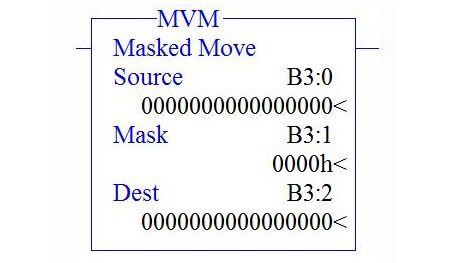
Masked Move Instruction Block Diagram

Masked Move Instruction in PLC

MVM Instruction Description

There are three parameters in MVM,

Source :

It is the address of the data you wants to move.

Mask :

Address of the mask through which the instruction moves data. The mask acts like a filter    for the destination.

Destination :

It is the address where the instruction moves the data.

There are three ways to give mask address,

  1. To enter a hexadecimal mask: type the hexadecimal value followed by the letter H (Hexadecimal).
  2. To enter a binary mask: type the binary value followed by the letter B (Binary).
  3. To enter a decimal mask: type the decimal value.

Note : RSLogix will make any necessary conversion and display the hexadecimal value.

MVM Instruction Function :

Activation of mask bit pattern will move the data in Source address to destination address. Move function will not happen until mask bit is activated.

Example 1

When the rung condition goes true,

Case 1

Output When Mask Bit is not activated,
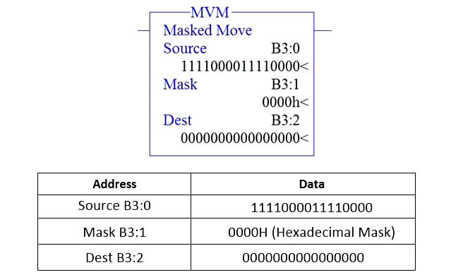
MVM PLC Block

Case 2

Output When Mask Bit is activated,
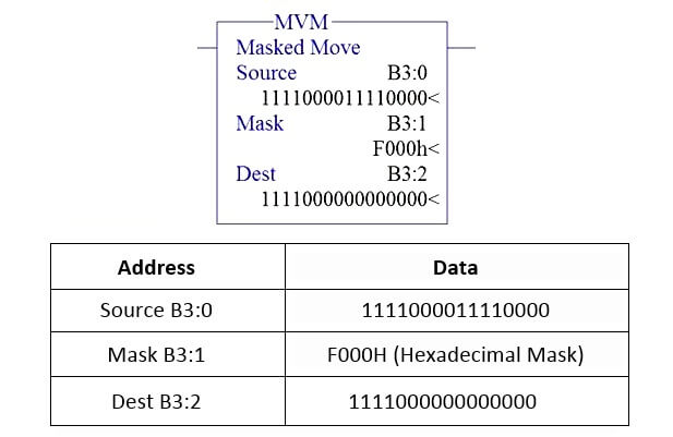
Masked Move Instruction Block Diagram

Example 2

When the rung condition goes true,

Case 1

Output When Mask Bit is not activated,
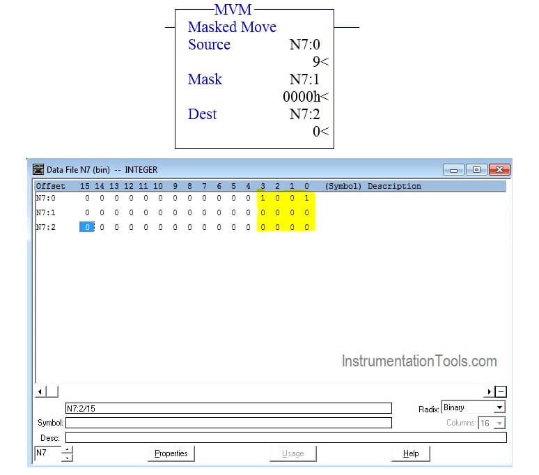
Masked Move Instructions

Case 2

Output When Mask Bit is activated,
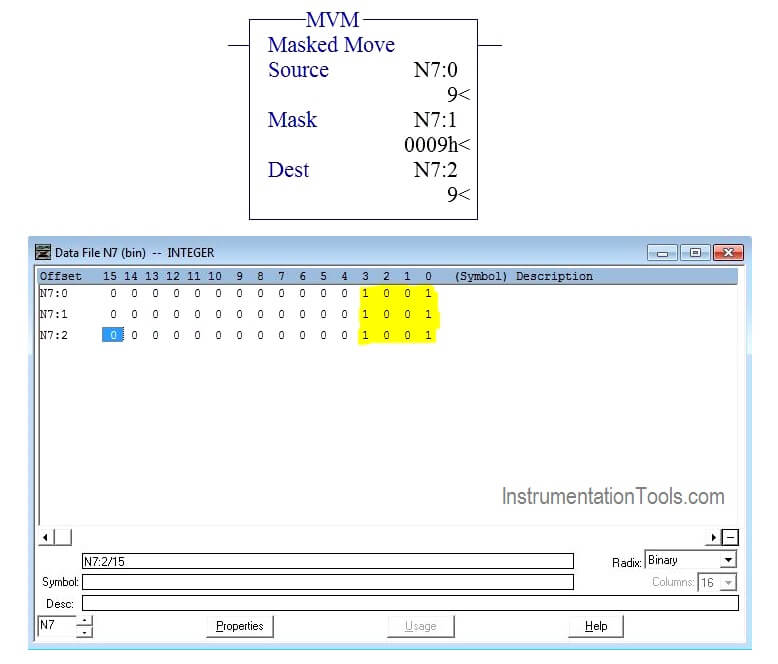
Mask Command in PLC

Example PLC Program using MVM Instruction

In this program, When N7:2 equals to the value 9, turn ON O:0/0,
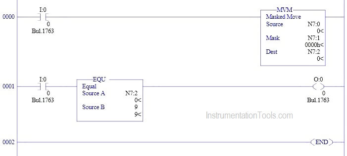
PLC Program using Mask Instruction

Program Description

 Rung 0000

When input condition goes true (I:0/0 turns “ON”),MVM instruction will move the data in N7:0 to N7:2.

Rung 0001

Equal block is used from comparator function to turn on O: 0/0 when N7:2 equal 9.

Conclusion

The above explained concept for Masked Move is for example only. We can use this example program to understand the working of MVM instruction in AB PLC.

Author : Hema Sundaresan

If you liked this article, then please subscribe to our YouTube Channel for PLC and SCADA video tutorials.

You can also follow us on Facebook and Twitter to receive daily updates.

Read Next:

PLC Analog Input Scaling

SCADA for Substation

PLC Counter Instruction

Features of SCADA

PLC Troubleshooting

Don't Miss Our Updates
Be the first to get exclusive content straight to your email.
We promise not to spam you. You can unsubscribe at any time.
Invalid email address
You've successfully subscribed !

Continue Reading

#15 PLC Best Practices – Safe State when PLC Restarts
WHILE DO Statement in SCL Language
Finding the Best PLC for Your Project – Tips and Tricks
Basics of Ladder Diagram in PLC Programming
Tutorial: Siemens Communication between PLCs using I-Device
What is PLC Redundancy?
Share This Article
Facebook Whatsapp Whatsapp LinkedIn Copy Link
Share
Leave a Comment

Leave a Reply Cancel reply

Your email address will not be published. Required fields are marked *

Stay Connected

128.3kFollowersLike
69.1kFollowersFollow
210kSubscribersSubscribe
38kFollowersFollow

Categories

Explore More

Types of PLC Memory
Main differences between Sinking and Sourcing Circuits
CW and CCW Operation of Motor from Same Push button
Statement List (STL) to Find Highest Value
Motor Control Signal Interface
PLC Programming for Traffic Barrier Control
Electric Motor Forward Reverse with Repeat Cycle PLC Logic
PLC Program for Positive Edge Pulse Output for One Scan Cycle

Keep Learning

Yokogawa DCS CPU

System Cabinet Health Checks – PLC and DCS Industrial Automation

Best Practices of PLC Wiring

Best Practices of PLC Wiring – Programmable Logic Controller

Safety PLC Coding Practices

Safety PLC Coding Practices – Programming Recommendations

Free Mitsubishi PLC Online Training Courses

Free Mitsubishi PLC Online Training Course and Tutorials

PLC Program for Boolean Expression

PLC Program for Boolean Expression

Conveyor and Puncher PLC Program

Toggle Switch & Sensor: Conveyor and Puncher PLC Program

Structured Control Language (SCL) Elements

Value Assignments in SCL Language – Single, Multiple, Combined

PLC Program for Two ways switch logic for staircase light

PLC Program for Two Way Switch Logic

Learn More

Unbonded Strain Gauge Principle

Unbonded Strain Gauge Principle

Digital Electronics Multiple Choice Questions

Flip Flops Objective Questions – Part 2

Tags in Functional Block Diagram in Studio 5000

Sheets, Tags, Elements in Functional Block Diagram of Studio 5000

Smoke Detection System Questions

Interview Questions on Smoke Detection System

Effects of Capillary Tubing on Pressure Measurement

Capillary Tubing Pressure Sensor Temperature & Elevation Problems

Digital Electronics Objective Questions

Digital Electronics Objective Questions – Set 2

Power Electronics Objective Questions

GTO Objective Questions and Answers

Thermal Power Plant

Thermal Power Plant – Basic Layout, Parts, Principle

Menu

  • About
  • Privacy Policy
  • Copyright

Quick Links

  • Learn PLC
  • Helping Hand
  • Part Time Job

YouTube Subscribe

Follow US
All rights reserved. Reproduction in whole or in part without written permission is prohibited.
Welcome Back!

Sign in to your account

Username or Email Address
Password

Lost your password?