Inst ToolsInst ToolsInst Tools
  • Courses
  • Automation
    • PLC
    • Control System
    • Safety System
    • Communication
    • Fire & Gas System
  • Instrumentation
    • Design
    • Pressure
    • Temperature
    • Flow
    • Level
    • Vibration
    • Analyzer
    • Control Valve
    • Switch
    • Calibration
    • Erection & Commissioning
  • Interview
    • Instrumentation
    • Electrical
    • Electronics
    • Practical
  • Q&A
    • Instrumentation
    • Control System
    • Electrical
    • Electronics
    • Analog Electronics
    • Digital Electronics
    • Power Electronics
    • Microprocessor
  • Request
Search
  • Books
  • Software
  • Projects
  • Process
  • Tools
  • Basics
  • Formula
  • Power Plant
  • Root Cause Analysis
  • Electrical Basics
  • Animation
  • Standards
  • 4-20 mA Course
  • Siemens PLC Course
Reading: Manually Interpreting Thermocouple Voltages
Share
Font ResizerAa
Inst ToolsInst Tools
Font ResizerAa
  • Courses
  • Design
  • PLC
  • Interview
  • Control System
Search
  • Courses
  • Automation
    • PLC
    • Control System
    • Safety System
    • Communication
    • Fire & Gas System
  • Instrumentation
    • Design
    • Pressure
    • Temperature
    • Flow
    • Level
    • Vibration
    • Analyzer
    • Control Valve
    • Switch
    • Calibration
    • Erection & Commissioning
  • Interview
    • Instrumentation
    • Electrical
    • Electronics
    • Practical
  • Q&A
    • Instrumentation
    • Control System
    • Electrical
    • Electronics
    • Analog Electronics
    • Digital Electronics
    • Power Electronics
    • Microprocessor
  • Request
Follow US
All rights reserved. Reproduction in whole or in part without written permission is prohibited.
Inst Tools > Blog > Temperature Measurement > Manually Interpreting Thermocouple Voltages

Manually Interpreting Thermocouple Voltages

Last updated: May 27, 2018 4:04 pm
Editorial Staff
Temperature Measurement
No Comments
Share
4 Min Read
SHARE

The amount of voltage indicated by a voltmeter connected to a thermocouple is the difference between the voltage produced by the measurement junction (the point where the two dissimilar metals join at the location we desire to sense temperature at) and the voltage produced by the reference junction (the point where the thermocouple wires join to the voltmeter wires):
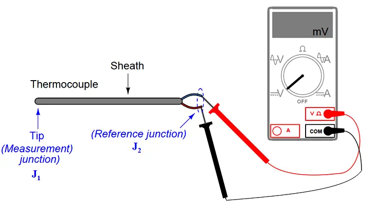
thermocouple voltages

Vmeter = VJ1 − VJ2

This makes thermocouples inherently differential sensing devices: they generate a measurable voltage in proportion to the difference in temperature between two locations. This inescapable fact of thermocouple circuits complicates the task of interpreting any voltage measurement obtained from a thermocouple. In order to translate a voltage measurement produced by a voltmeter connected to a thermocouple, we must add the voltage produced by the measurement junction (VJ2) to the voltage indicated by the voltmeter to find the voltage being produced by the measurement junction (VJ1). In other words, we manipulate the previous equation into the following form:

VJ1 = VJ2 + Vmeter

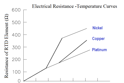
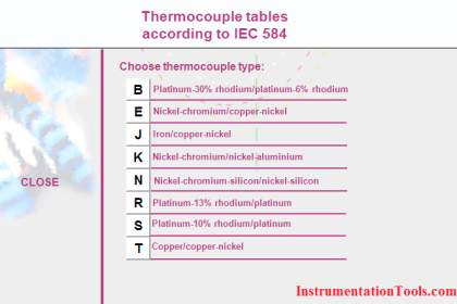
We may ascertain the reference junction voltage by placing a thermometer near that junction (where the thermocouple wire attaches to the voltmeter test leads) and referencing a thermocouple table showing temperatures and corresponding voltages for that thermocouple type. Then, we may take the voltage sum for VJ1 and re-reference that same table, finding the temperature value corresponding to the calculated measurement junction voltage. The National Institute of Standards and Technology (NIST) in the United States publishes tables showing junction voltages and temperatures for standardized thermocouple types. While it is possible to mathematically model a thermocouple junction’s voltage in the same way we may model an RTD’s resistance, the functions for thermocouples are less linear than for RTDs, and so tables are greatly preferred for practical use.

Also Check : Thermocouple Tables

To illustrate, suppose we connected a voltmeter to a type K thermocouple and measured 14.30 millivolts. A thermometer situated near the thermocouple wire / voltmeter junction point shows an ambient temperature of 73 degrees Fahrenheit. Referencing a table of voltages for type K thermocouples (in this case, the NIST “ITS-90” reference standard), we see that a type K junction at 73 degrees Fahrenheit corresponds to 0.910 millivolts. Adding this figure to our meter measurement of 14.30 millivolts, we arrive at a sum of 15.21 millivolts for the measurement (“hot”) junction. Going back to the same table of values, we see 15.21 millivolts falls between 701 and 702 degrees Fahrenheit. Linearly interpolating between the table values (15.203 mV at 701 oF and 15.226 mV at 702 oF), we may more precisely determine the measurement junction to be 701.3 degrees Fahrenheit.

The process of manually taking voltage measurements, referencing a table of millivoltage values, performing addition, then re-referencing the same table is rather tedious. Compensation for the reference junction’s inevitable presence in the thermocouple circuit is something we must do, but it is not something that must always be done by a human being. The next subsection discusses ways to automatically compensate for the effect of the reference junction, which is the only practical alternative for continuous thermocouple-based temperature instruments.

Also Check : Thermocouple Calculator

Credits : Tony R. Kuphaldt – Creative Commons Attribution 4.0 License

Don't Miss Our Updates
Be the first to get exclusive content straight to your email.
We promise not to spam you. You can unsubscribe at any time.
Invalid email address
You've successfully subscribed !

Continue Reading

Spiral Bimetallic Thermometer Principle
Thermowell Insertion and Immersion Length
Calculate Temperature Coefficient of RTD
Thermocouple and its Principle
Why 4 wire RTD Measurement Accuracy is better than 2 and 3 wire RTD?
Testing a Thermocouple With a Multimeter
Share This Article
Facebook Whatsapp Whatsapp LinkedIn Copy Link
Share
Leave a Comment

Leave a Reply Cancel reply

Your email address will not be published. Required fields are marked *

Stay Connected

128.3kFollowersLike
69.1kFollowersFollow
210kSubscribersSubscribe
38kFollowersFollow

Categories

Explore More

Foundation Fieldbus Temperature Transmitter Configuration
Non-contact Pyrometers Characteristics
Thermocouple Construction
Why we use Wheatstone bridge in RTD?
What is a Thermocouple ?
Thermocouple Questions and Answers
Questions on Thermocouple and Pyrometer
Thermal Imaging Temperature Measurement

Keep Learning

RTD Construction

Introduction to RTDs

Temperature Transmitter Formula

Calculate Temperature Transmitter Output

Difference Between RTD, Thermocuples and Thermistors

Difference Between RTD, Thermocouple and Thermistor

Thermocouple Standard

Thermocouple Details

Three Wire RTD Wheatstone bridge Circuit

RTD Wheatstone Bridge Circuits

RTD Calibration

RTD Calibration

Peltier Effect

Peltier Effect Theory

RTD Questions & Answers

RTD Questions and Answers

Learn More

Emergency ShutDown Valve Working Principle

ESDV : How it Works ?

pH Analyzers Interview Questions Answers

pH Analyzer Interview Questions and Answers

Deluge Valve Operation using Solenoid Valve Animation

Deluge Valve Operation

Electrical Machines Questions and Answers

Transformer Open Circuit and Short Circuit Test

What is a Memristor

What is a Memristor? Principle, Advantages, Applications

transistor-terminals

Basics of Transistors

Power Electronics Objective Questions

Half Wave Diode Rectifier Quiz

Routine Tests of Transformers

Transformer Testing – Routine Tests of Transformers

Menu

  • About
  • Privacy Policy
  • Copyright

Quick Links

  • Learn PLC
  • Helping Hand
  • Part Time Job

YouTube Subscribe

Follow US
All rights reserved. Reproduction in whole or in part without written permission is prohibited.
Welcome Back!

Sign in to your account

Username or Email Address
Password

Lost your password?