This article discusses the Mail Box Program with a Counter function using a Schneider PLC and Ecostruxure Software. This Mail Box has a door that is used to take letters and a hole to put letters in. This Mail Box uses sensors to detect incoming and outgoing mail. Letters entered into the Post Box will be counted and when the Mail Box Door is Opened to collect the letter, the counter data will be Reset.
This Mail Box have 3 lamp indicators, the Green lamp will turn ON if the amount of letters is Greater Than “0” and Less Than “10”, the Yellow lamp will turn ON if the amount of letters is Greater Than Or Equal To”10″, and if the amount of letters in the Mail Box “15” then the Red lamp will be ON, indicating that the Mail Box is full.
Mail Box Automation
This PLC program has 2 buttons and 2 sensors, the PB_START (I0.0) button is used to turn ON the system and the PB_STOP (I0.1) button is used to turn OFF the system. The SENS_IN (I0.2) sensor is used to detect letters entering the Mail box and SENS_OUT (I0.3) is used to detect outgoing letters.
The system will Run when the PB_START (I0.0) button is Pressed. The system will be Stop if the PB_STOP (I0.1) button is Pressed.
If A Letter is Entered
If the SENS_IN (I0.2) sensor is Active, the counter value in memory word COUNT_MAIL (MW0) will increase (+1) and the Green lamp indicator GREEN_LAMP (Q0.0) will turn ON.
When the counter value in memory word COUNT_MAIL (MW0) is Greater Than Or Equal to”10″, the Yellow lamp indicator YELLOW_LAMP (Q0.1) will turn ON and the Green lamp indicator GREEN_LAMP (Q0.0) will turn OFF.
If the counter value in the memory word COUNT_MAIL (MW0) is equal to “1” then the Yellow lamp indicator YELLOW_LAMP (Q0.1) will turn OFF and the Red lamp indicator RED_LAMP (Q0.2) will turn ON.
If the Letter is Taken
If the SENS_OUT (I0.3) sensor is Active, the Green GREEN_LAMP (Q0.0), Yellow YELLOW_LAMP (Q0.1), and Red RED_LAMP (Q0.2) indicator lamps will turn OFF and the counter value in memory word COUNT_MAIL (MW0) will be Reset to “0”.
Project Addressing
| Comment | Input (I) | Output (Q) | Memory Word | Memory Bits | Timer |
| PB_START | I0.0 | ||||
| PB_STOP | I0.1 | ||||
| SENS_IN | I0.2 | ||||
| SENS_OUT | I0.3 | ||||
| GREEN_LAMP | Q0.0 | ||||
| YELLOW_LAMP | Q0.1 | ||||
| RED_LAMP | Q0.2 | ||||
| COUNT_MAIL | MW0 | ||||
| SYSTEM_ON | M0 | ||||
| IR_YELLOW_LAMP | M1 | ||||
| IR_RED_LAMP | M2 |
Programming with Schneider PLC
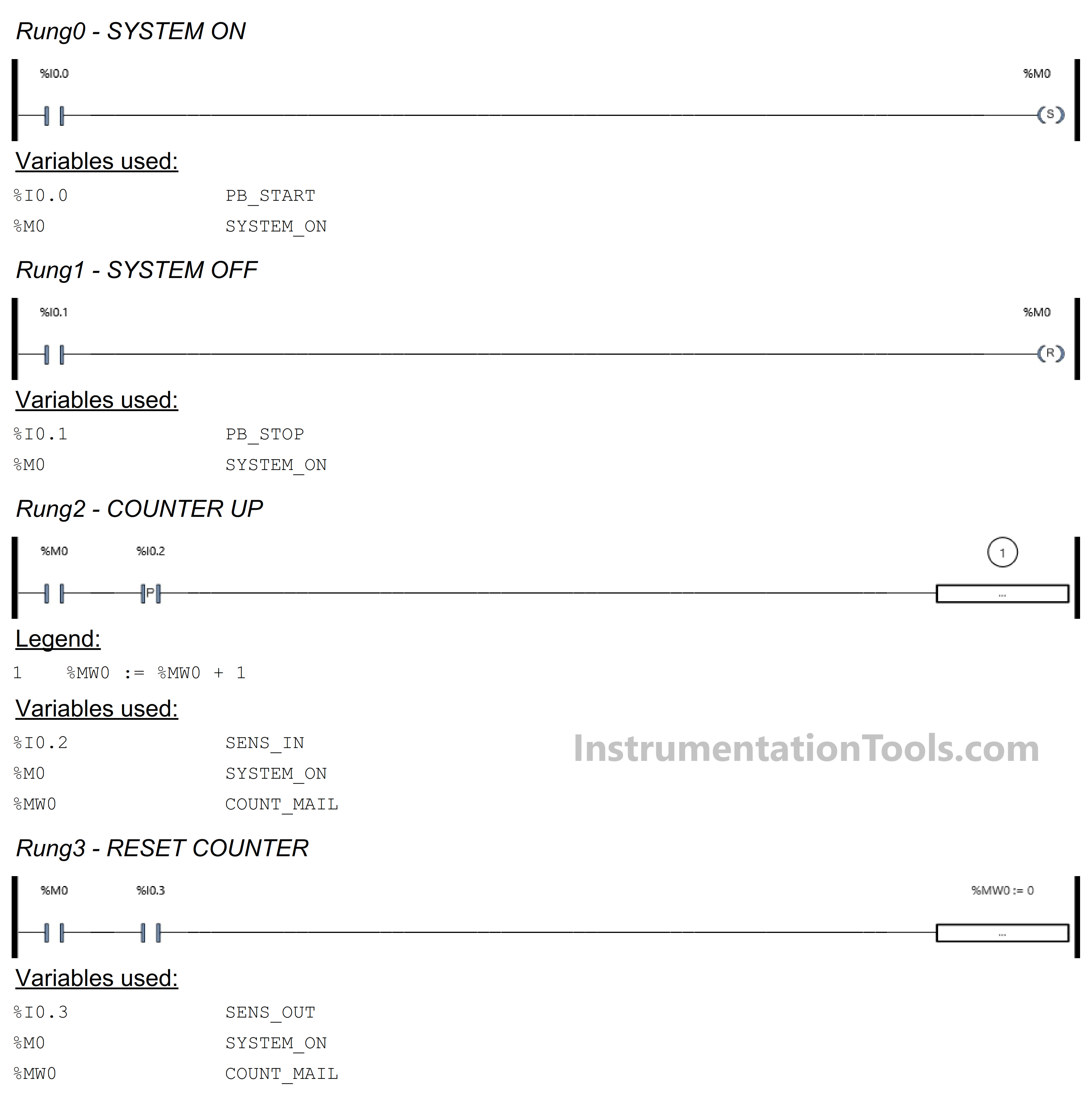
RUNG 0 (SYSTEM ON)
In this Rung, the memory bit SYSTEM_ON (M0) will be in HIGH state if the PB_START (I0.0) button is Pressed. The memory bit SYSTEM_ON (M0) remains in the HIGH state even though the PB_START (I0.0) button has been Released, because it uses the SET Coil Instruction.
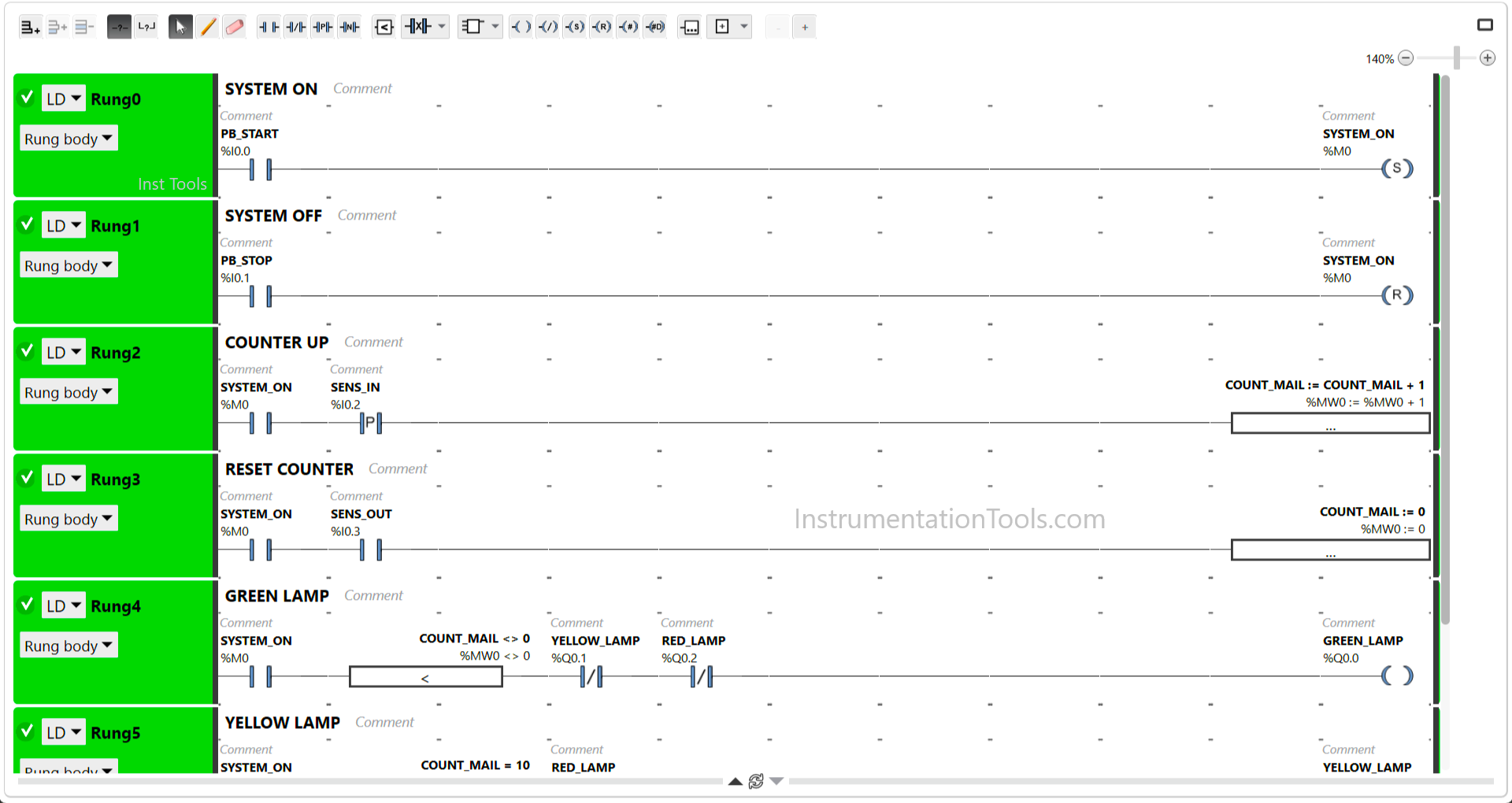
RUNG 1 (SYSTEM OFF)
In this Rung, the memory bit SYSTEM_ON (M0) will become LOW state if the PB_STOP (I0.1) button is Pressed. Because it uses the RESET Coil Instruction.
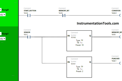
RUNG 2 (COUNTER UP)
In this Rung, the value in memory word COUNT_MAIL (MW0) will increase (+1) if the NO contact of memory bit SYSTEM_ON (M0) and Sensor SENS_IN (I0.2) is in the HIGH state.
RUNG 3 (RESET COUNTER)
In this rung, the value in memory word COUNT_MAIL (MW0) will be Reset to zero “0” if the NO contact of memory bit SYSTEM_ON (M0) and Sensor SENS_OUT (I0.3) in the HIGH state.
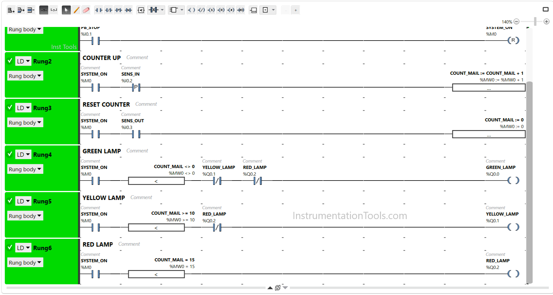
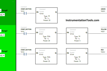
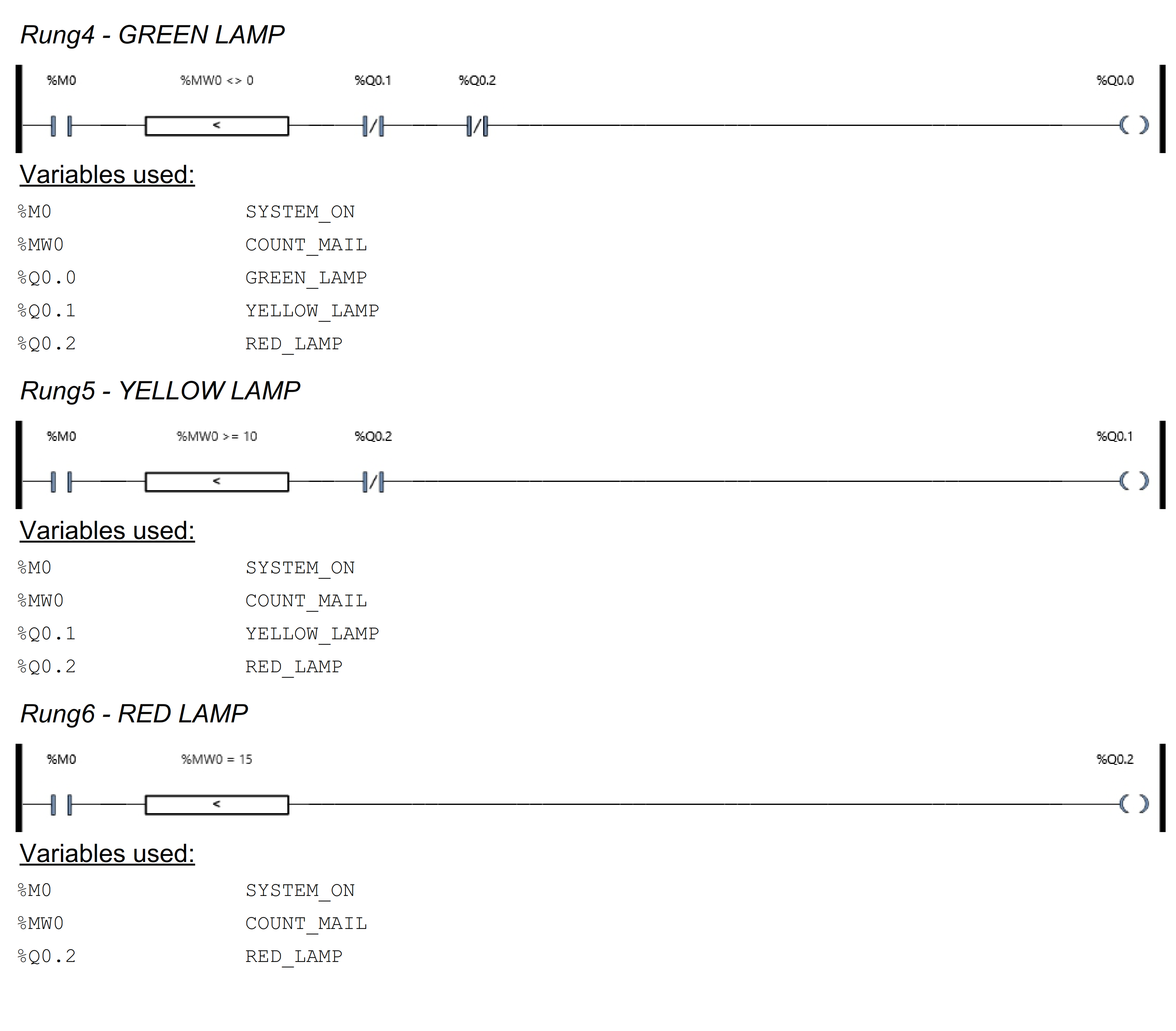
RUNG 4 (GREEN LAMP)
In this Rung, the GREEN_LAMP (Q0.0) Output will be ON if the NO contact of memory bit SYSTEM_ON (M0) and the value in memory word COUNT_MAIL (MW0) is not equal to “0”.
If the NC contacts of YELLOW_LAMP (Q0.1) and RED_LAMP (Q0.2) are ON, then the GREEN_LAMP (Q0.0) output will be OFF.
RUNG 5 (YELLOW LAMP)
In this Rung, the YELLOW_LAMP (Q0.1) Output will be ON if the NO contact of memory bit SYSTEM_ON (M0) and the value in memory word COUNT_MAIL (MW0) is Greater Than Or Equal To “10”.
If the NC contact of RED_LAMP (Q0.2) is ON, then the YELLOW_LAMP (Q0.1) output will be OFF.
RUNG 6 (RED LAMP)
In this Rung, Output RED_LAMP (Q0.2) will be ON if the NO contact of memory bit SYSTEM_ON (M0) and the value in memory word COUNT_MAIL (MW0) is Equal to “15”.
Read Next:
- PLC Program for Password Management
- PLC Program Sequential Batch Mixing System
- Electrical Dosing Pump PLC Programming Logic
- Schneider PLC Example for Star-Delta System
- Medium-Level PLC Exercise in Automation