Inst ToolsInst ToolsInst Tools
  • Courses
  • Automation
    • PLC
    • Control System
    • Safety System
    • Communication
    • Fire & Gas System
  • Instrumentation
    • Design
    • Pressure
    • Temperature
    • Flow
    • Level
    • Vibration
    • Analyzer
    • Control Valve
    • Switch
    • Calibration
    • Erection & Commissioning
  • Interview
    • Instrumentation
    • Electrical
    • Electronics
    • Practical
  • Q&A
    • Instrumentation
    • Control System
    • Electrical
    • Electronics
    • Analog Electronics
    • Digital Electronics
    • Power Electronics
    • Microprocessor
Search
  • Books
  • Software
  • Projects
  • Process
  • Tools
  • Basics
  • Formula
  • Power Plant
  • Root Cause Analysis
  • Electrical Basics
  • Animation
  • Standards
  • 4-20 mA Course
  • Siemens PLC Course
Reading: Magnetostrictive Level Measurement
Share
Notification Show More
Font ResizerAa
Inst ToolsInst Tools
Font ResizerAa
  • Courses
  • Design
  • PLC
  • Interview
  • Control System
Search
  • Courses
  • Automation
    • PLC
    • Control System
    • Safety System
    • Communication
    • Fire & Gas System
  • Instrumentation
    • Design
    • Pressure
    • Temperature
    • Flow
    • Level
    • Vibration
    • Analyzer
    • Control Valve
    • Switch
    • Calibration
    • Erection & Commissioning
  • Interview
    • Instrumentation
    • Electrical
    • Electronics
    • Practical
  • Q&A
    • Instrumentation
    • Control System
    • Electrical
    • Electronics
    • Analog Electronics
    • Digital Electronics
    • Power Electronics
    • Microprocessor
Follow US
All rights reserved. Reproduction in whole or in part without written permission is prohibited.
Inst Tools > Blog > Level Measurement > Magnetostrictive Level Measurement

Magnetostrictive Level Measurement

Last updated: December 17, 2017 3:23 pm
Editorial Staff
Level Measurement
No Comments
Share
6 Min Read
SHARE

A variation on the theme of echo-based level instruments, where the level of some process material in a vessel is measured by timing the travel of a wave between the instrument and the material interface, is one applied to float-type instruments: magnetostriction.

In a magnetostrictive level instrument, liquid level is sensed by a lightweight, donut-shaped float containing a magnet. This float is centered around a long metal rod called a waveguide, hung vertically in the process vessel (or hung vertically in a protective cage like the type used for displacement-style level instruments) so that the float may rise and fall with process liquid level. The magnetic field from the float’s magnet at that point, combined with the magnetic field produced by an electric current pulse periodically sent through the rod, generates a torsional stress pulse at the precise location of the float. This torsional (twisting) stress travels at the speed of sound through the rod toward either end. At the bottom end is a dampener device designed to absorb the mechanical wave .

One might argue that a magnetostrictive instrument is not an “echo” technology in the strictest sense of the word. Unlike ultrasonic, radar, and laser instruments, we are not reflecting a wave off a discontinuous interface between materials. Instead, a mechanical wave (pulse) is generated at the location of a magnetic float in response to an electrical pulse. However, the principle of measuring distance by the wave’s travel time is the same. At the top end of the rod (above the process liquid level) is a sensor and electronics package designed to detect the arrival of the mechanical wave. A precision electronic timing circuit measures the time elapsed between the electric current pulse (called the interrogation pulse) and the received mechanical pulse. So long as the speed of sound through the metal waveguide rod remains fixed, the time delay is strictly a function of distance between the float and the sensor, which we already know is called ullage.

The following photograph (left) and illustration (right) show a magnetostrictive level transmitter propped up against a classroom wall and the same style of transmitter installed in a liquid-holding vessel, respectively:

magnetostrictive level transmitter principle

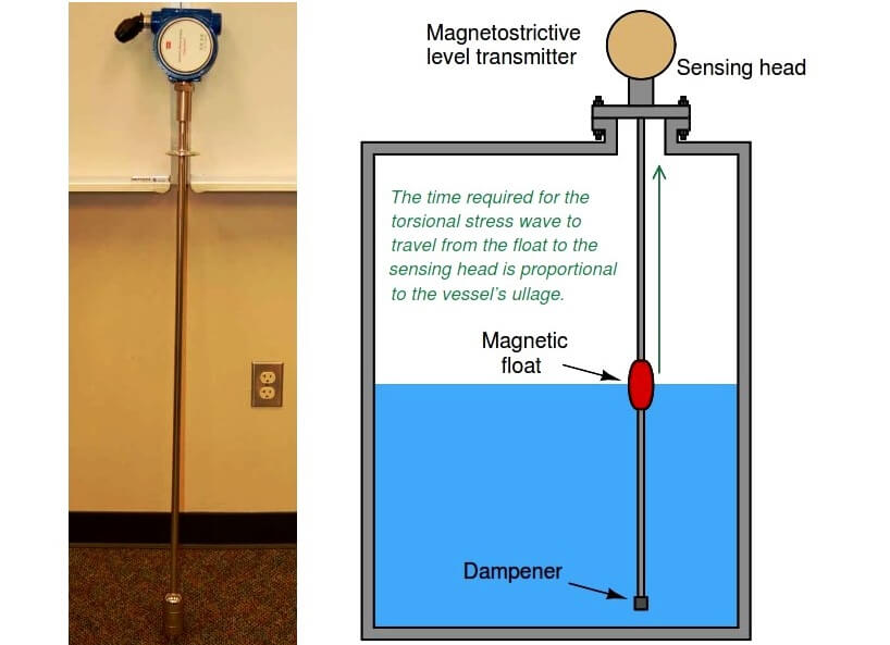
The design of this instrument is reminiscent of a guided-wave radar transmitter, where a metal waveguide hangs vertically into the process liquid, guiding a pulse to the sensor head where the sensitive electronic components are located. The major difference here is that the pulse is a sonic vibration traveling through the metal of the waveguide rod, not an electromagnetic pulse as is the case with radar. Like all sound waves, the torsional pulse in a magnetostriction-based level transmitter is much slower-traveling  than electromagnetic waves.

Also Read : Buoyant Force Level Instruments Principle

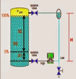
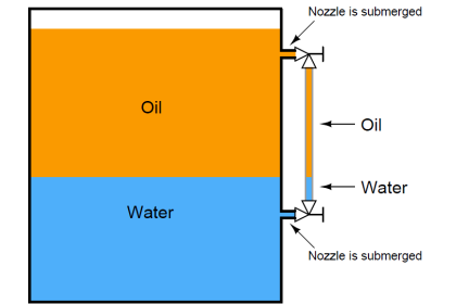
It is even possible to measure liquid-liquid interfaces with magnetostrictive instruments. If the waveguide is equipped with a float of such density that it floats on the interface between the two liquids (i.e. the float is denser than the light liquid and less dense than the heavy liquid), the sonic pulse generated in the waveguide by that float’s position will represent interface level. Magnetostrictive instruments may even be equipped with two floats: one to sense a liquid-liquid interface, and the other to sense the liquid-vapor interface, so that it may measure both the interface and total levels simultaneously just like a guided-wave radar transmitter:

Magnetostrictive instruments

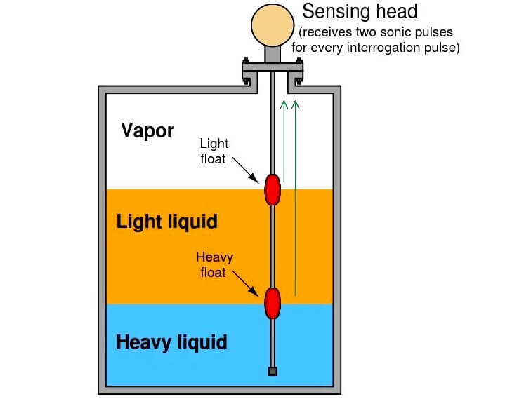
With such an instrument, each electrical “interrogation” pulse returns two sonic pulses to the sensor head: the first pulse representing the total liquid level (upper, light float) and the second pulse representing the interface level (lower, heavy float). If the instrument has digital communication capability (e.g. HART, FOUNDATION Fieldbus, Profibus, etc.), both levels may be reported to the control system over the same wire pair, making it a “multivariable” instrument.

Perhaps the greatest limitation of magnetostrictive level instruments is mechanical interference between the float and the rod. In order for the magnetostrictive effect to be strong, the magnet inside the float must be in close proximity to the rod. This means the inside diameter of the donut-shaped float must fit closely to the outside diameter of the waveguide. Any fouling of the waveguide’s or float’s surfaces by suspended solids, sludge, or other semi-solid materials may cause the float to bind and therefore not respond to changes in liquid level.

Credits : Tony R. Kuphaldt – Creative Commons Attribution 4.0 License

Don't Miss Our Updates
Be the first to get exclusive content straight to your email.
We promise not to spam you. You can unsubscribe at any time.
Invalid email address
You've successfully subscribed !

Continue Reading

Magnetic Float Level Switch Working Animation
Why Measure Level
Air Purge or Air Bubbler Level Measurement
Non Contact RADAR Level Transmitter Principle, Limitations, Design, Installation and Calibration
Open Tank Level Measurement using DP Transmitters Animation
Radar Tank Gauging
Share This Article
Facebook Whatsapp Whatsapp LinkedIn Copy Link
Share
Leave a Comment

Leave a Reply Cancel reply

Your email address will not be published. Required fields are marked *

Stay Connected

128.3kFollowersLike
69.1kFollowersFollow
208kSubscribersSubscribe
38kFollowersFollow

Categories

Explore More

Difference between Transparent Level Gauge and Reflex Level Gauge
Microwave Barrier Level Switch Working Principle
Types of Level Gauges
Zero Elevation and Zero Suppression in Level Measurement
Open Tank DP Level Transmitter Calibration
What is a Level Switch? Types of Level Switches
Laser Level Measurement Principle
Guided Wave Radar – Principle, Limitations, Installation

Keep Learning

Tuning Fork Level Switch principle

Tuning Fork Level Switch Principle

Reflex Level Gauge Parts

What is Reflex Level Gauge?

Capacitive Level Measurement Principle

Capacitive Level Measurement

Level Sensors

Advantages & Disadvantages of Level Measurement Systems

Magnetically coupled float indicates liquid level

What are Mechanical Level Indicators? – Classification & Principle

Capacitance Level measurement principle

Capacitance Level Sensor Principle, Limitations, Installation & Calibration

Interface level Measurement

Interface Level Measurement using DP Transmitter

level gauge

Basics of Sight Glass Level Gauge

Learn More

3 to 8 Line Decoder Circuit Diagram

3 to 8 Line Decoder PLC Ladder Diagram

SCADA Features

Features of SCADA

Industrial safety Objective Questions and Answers

Top 10 Industrial safety Objective Questions

Single-Bed Demineralizer

Demineralizers

Metal Seated Ball Valves

Metal Seated Valves and Soft Seated Valves : Differences

Scan cycle of a Siemens PLC

OB1 – Main Cyclic Organization Block in TIA Portal

Mass Spectrometer Questions and Answers

Liquid Chromatograph- Mass Spectrometer

why-symmetrical-components-used

Why Symmetrical Components Used for Unbalanced faults in Power System

Follow US
All rights reserved. Reproduction in whole or in part without written permission is prohibited.
Welcome Back!

Sign in to your account

Username or Email Address
Password

Lost your password?