Inst ToolsInst ToolsInst Tools
  • Courses
  • Automation
    • PLC
    • Control System
    • Safety System
    • Communication
    • Fire & Gas System
  • Instrumentation
    • Design
    • Pressure
    • Temperature
    • Flow
    • Level
    • Vibration
    • Analyzer
    • Control Valve
    • Switch
    • Calibration
    • Erection & Commissioning
  • Interview
    • Instrumentation
    • Electrical
    • Electronics
    • Practical
  • Q&A
    • Instrumentation
    • Control System
    • Electrical
    • Electronics
    • Analog Electronics
    • Digital Electronics
    • Power Electronics
    • Microprocessor
  • Request
Search
  • Books
  • Software
  • Projects
  • Process
  • Tools
  • Basics
  • Formula
  • Power Plant
  • Root Cause Analysis
  • Electrical Basics
  • Animation
  • Standards
  • 4-20 mA Course
  • Siemens PLC Course
Reading: Magnetic Float Level Switch Working Animation
Share
Font ResizerAa
Inst ToolsInst Tools
Font ResizerAa
  • Courses
  • Design
  • PLC
  • Interview
  • Control System
Search
  • Courses
  • Automation
    • PLC
    • Control System
    • Safety System
    • Communication
    • Fire & Gas System
  • Instrumentation
    • Design
    • Pressure
    • Temperature
    • Flow
    • Level
    • Vibration
    • Analyzer
    • Control Valve
    • Switch
    • Calibration
    • Erection & Commissioning
  • Interview
    • Instrumentation
    • Electrical
    • Electronics
    • Practical
  • Q&A
    • Instrumentation
    • Control System
    • Electrical
    • Electronics
    • Analog Electronics
    • Digital Electronics
    • Power Electronics
    • Microprocessor
  • Request
Follow US
All rights reserved. Reproduction in whole or in part without written permission is prohibited.
Inst Tools > Blog > Animation > Magnetic Float Level Switch Working Animation

Magnetic Float Level Switch Working Animation

Last updated: October 13, 2017 4:09 pm
Editorial Staff
Animation How It Works Level Measurement Switches
8 Comments
Share
2 Min Read
SHARE

Magnetic Float Switch Working Animation

The purpose of a float level switch is to open or close a circuit as the level of a liquid rises or falls.  All float operated liquid level controls operate on the basic buoyancy principle which states “the buoyancy force action on an object is equal to the mass of liquid displaced by the object.” As a result, floats ride on the liquid surface partially submerged and move the same distance the liquid level moves. Because of this, they are normally used for narrow level differential applications such as high level alarm or low level alarm.

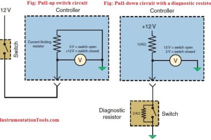
To complete a circuit, float switches utilize a magnetic reed switch, which consists of two contacts sealed in a glass tube.  When a magnet comes close to the two contacts, they become attracted to each other and touch, allowing current to pass through.  When the magnet moves away, the contacts demagnetize and separate (breaking the circuit), as shown below figure.

Magnetic Float Switches Principle

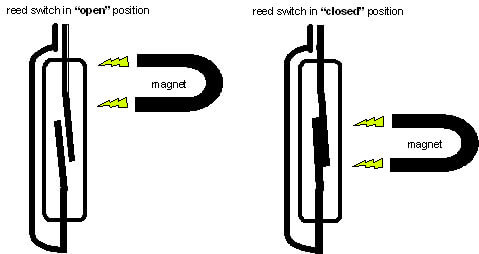
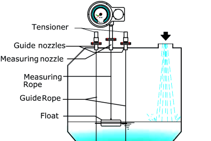
In a float switch, the magnetic reed switch is hermetically sealed in a stem, most often made from plastic or stainless steel.  The float encases a sealed magnet, which moves up and down the length of the stem as a fluid level rises and falls.  As the magnet passes by the contacts in the encased reed switch, they touch and complete a circuit between the two lead wires. The Open or Close of the Contacts indicates the High or Low Alarm.

Magnetic Float Switch Working Animation-2

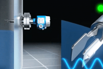
Here in our Animation, The raise in liquid level lifts the float and this in turn moves the magnet closer to the reed switch. when magnet comes near to reed switch, the output contact changes. The change in contact is a signal of liquid level raise or vice versa.

Also Read: Analyzers Working Principles

Don't Miss Our Updates
Be the first to get exclusive content straight to your email.
We promise not to spam you. You can unsubscribe at any time.
Invalid email address
You've successfully subscribed !

Continue Reading

How to Calibrate Temperature Switch? – Instrument Basics
Open and Closed Tank Level Calculations
Argonite Fire Suppression System Working Principle
Flare Knockout Drums Working Animation
Pull Cord Switch Working Principle
Piston Flow Meters Working Principle with Animation
Share This Article
Facebook Whatsapp Whatsapp LinkedIn Copy Link
Share
8 Comments
  • Murthy M says:
    September 4, 2015 at 5:13 am

    You really explained in really good way & with animation is super.

    Reply
  • Abhishek Singh Tomar says:
    May 30, 2016 at 5:33 am

    Very helpfull for us

    Reply
  • Mohan says:
    May 30, 2016 at 3:17 pm

    What is the difference between level switch and float switch??????

    Reply
  • Reuben says:
    June 8, 2016 at 4:12 am

    helpful indeed

    Reply
  • jamsheer says:
    June 16, 2016 at 7:05 am

    can we change the level set point in this switch???

    Reply
  • Mahtab says:
    October 1, 2016 at 10:05 am

    Why we use 3 pressure switch same set point in same flow line.

    Reply
  • Mithun Sahani says:
    December 19, 2016 at 5:46 pm

    Very nice

    Reply
  • nabisab says:
    February 18, 2019 at 10:18 pm

    sir very good video with logic

    Reply

Leave a Reply Cancel reply

Your email address will not be published. Required fields are marked *

Stay Connected

128.3kFollowersLike
69.1kFollowersFollow
210kSubscribersSubscribe
38kFollowersFollow

Categories

Explore More

How can we use a DP Flow Transmitter for Level Measurement
Relay Principle & its Types
Rotary Abutment Flow Meters Working Principle and Animation
Deluge Valve Operation
Capacitance Level Measurement Working Principle
Solenoid Valve Working Animation
Vibrating Fork Level Switch Working Animation
Hydrostatic Level Measurement

Keep Learning

Dome Valve Principle

Dome Valve Working Principle

Boiler Level Switch

Float level switch Principle

Displacer interface level measurement Calibration

Displacer Interface Level Measurement

Interface Level Measurement Selection Guide

Interface Level Measurement Selection Guide

Potentiometer Animation

Potentiometer Working Principle Animation

Open-Tank-DP-Level-Transmitter-with-Zero-Suppression-Calibration

DP Level Transmitter with Zero Suppression Calibration

Stilling wells

Stilling Wells for Level Measurement

Overview of Tank Gauging Technologies

Learn More

Step-by-step import export in FactoryTalk View

FactoryTalk View Studio – Import and Export Tutorial

P&ID Legend

What is a Legend? – Piping and Instrumentation Diagram

Stability and Uniformity of Temperature Bath

Stability and Uniformity of Temperature Bath

Time Response Analysis

Effect of Adding a Zero to a System

Safety Instrumented System Interview Questions Answers

Safety Instrumented System Interview Questions and Answers

Use Cryptographic checks for PLC

#5 PLC Best Practices – Cryptographic and Checksum Integrity Checks

Circuit Control Devices Multiple Choice Questions

Circuit Control Devices Multiple Choice Questions & Answers

PLC Program for Automatic Oil and Water Separation Process

Oil and Water Separation Process using PLC Programming

Menu

  • About
  • Privacy Policy
  • Copyright

Quick Links

  • Learn PLC
  • Helping Hand
  • Part Time Job

YouTube Subscribe

Follow US
All rights reserved. Reproduction in whole or in part without written permission is prohibited.
Welcome Back!

Sign in to your account

Username or Email Address
Password

Lost your password?