This article discusses a liquid temperature control system in a tank using Siemens TIA-Portal software. The system is designed to maintain the liquid temperature within the range of 32-45 degrees Celsius. The liquid temperature control system operates based on the principles of measurement, comparison, and action. Liquid can only be entered or removed from the tank manually through valves. The system is also equipped with a warning alarm feature that will activate if the temperature exceeds the maximum limit or falls below the minimum limit.
Program Objective
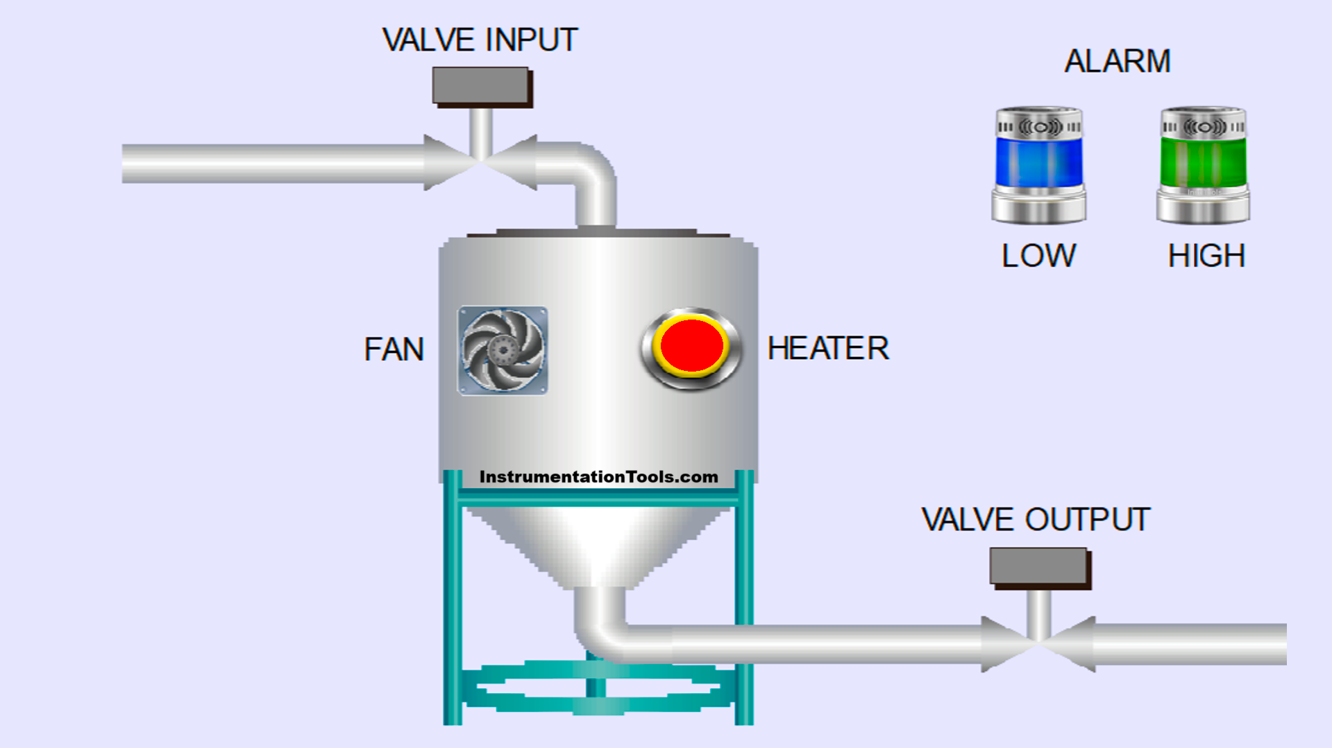
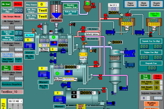
This system has an Input Valve and Output Valve Input Valve and an Output Valve, which are used to control the flow of liquid inside the tank. The Heater is used to raise the liquid temperature, while the Exhaust Fan is used to lower the liquid temperature.
Manual Operation:
- The Input Valve and Output Valve can be controlled manually using buttons.
- In Manual mode, both the Heater and the Exhaust Fan can only be activated through buttons.
Automatic Operation (Auto Mode):
- To activate Auto mode, the Selector Switch must be set to the Auto position.
- In this mode, the Heater and Exhaust Fan will operate automatically based on the need to maintain the liquid temperature.
- If the liquid temperature exceeds 45°C, the Exhaust Fan will turn On to cool the liquid.
- If the liquid temperature is below 32°C, the Heater will turn On to heat the liquid.
Safety Alarm:
- The indicator alarm will be ON if the liquid temperature reaches above 55°C or below 20°C. This indicates that the fluid temperature is outside normal limits and requires immediate action.
Liquid Temperature Control System
IO Mapping
| S.No. | Comment | Input (I) | Output(Q) | Memory Bit | Memory Word |
| 1 | PB_START | I0.0 | |||
| 2 | PB_STOP | I0.1 | |||
| 3 | AUTO/MANUAL | I0.2 | |||
| 4 | HEATER_BUTTON | I0.3 | |||
| 5 | EXHAUST_FAN_BUTTON | I0.4 | |||
| 6 | PB_VALVE_IN | I0.5 | |||
| 7 | PB_VALVE_OUT | I0.6 | |||
| 8 | VALVE_INPUT | Q0.0 | |||
| 9 | VALVE_OUTPUT | Q0.1 | |||
| 10 | HEATER | Q0.2 | |||
| 11 | EXHAUST_FAN | Q0.3 | |||
| 12 | ALARM_OVER_HEAT | Q0.4 | |||
| 13 | ALARM_LOW_TEMPERATURE | Q0.5 | |||
| 14 | SYSTEM_ON | M0.0 | |||
| 15 | HEATER_MANUAL | M0.1 | |||
| 16 | EXHAUST_FAN_MANUAL | M0.2 | |||
| 17 | EXHAUST_FAN_AUTO | M0.3 | |||
| 18 | HEATER_AUTO | M0.4 | |||
| 19 | PV_TEMPERATURE | MW10 |
Siemens TIA Portal Project
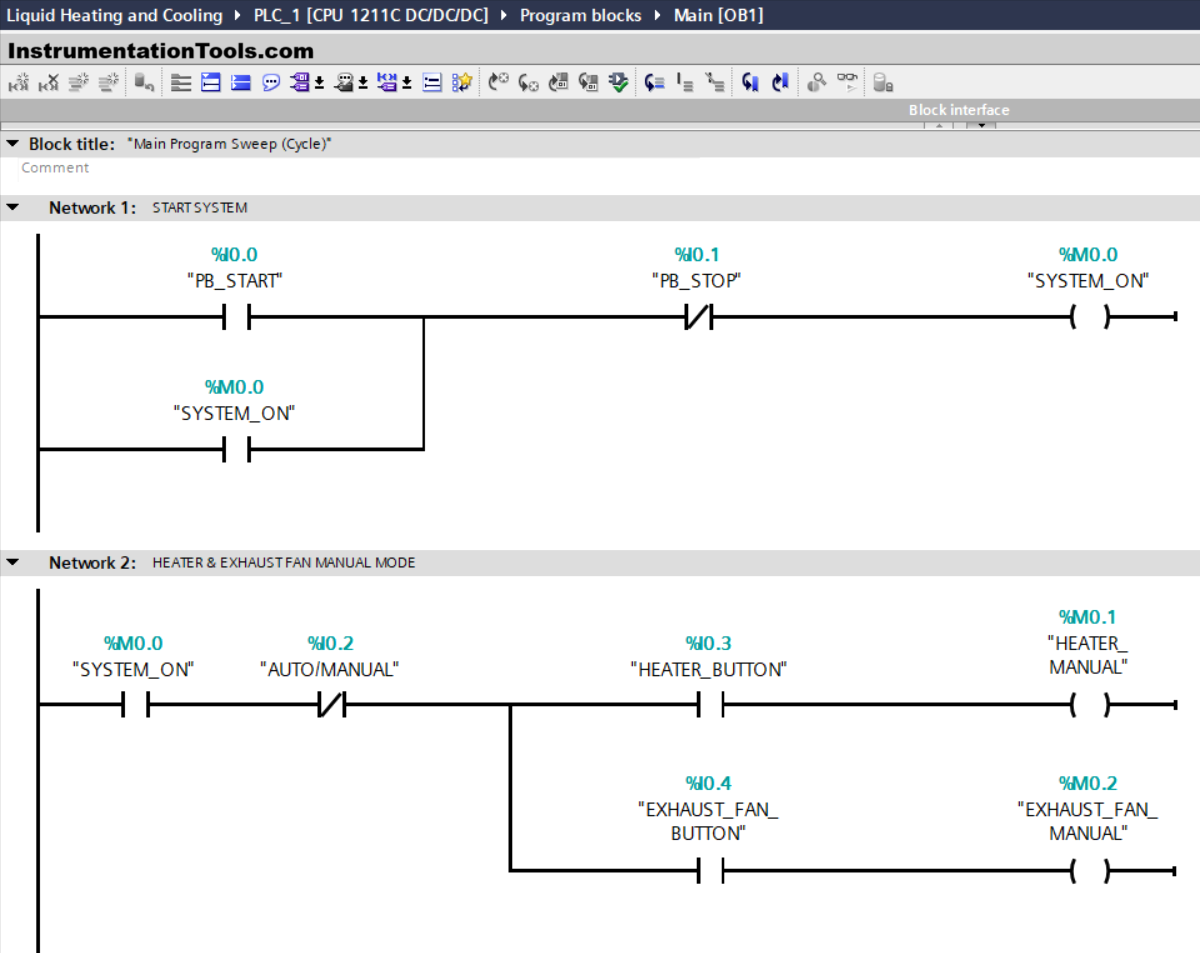
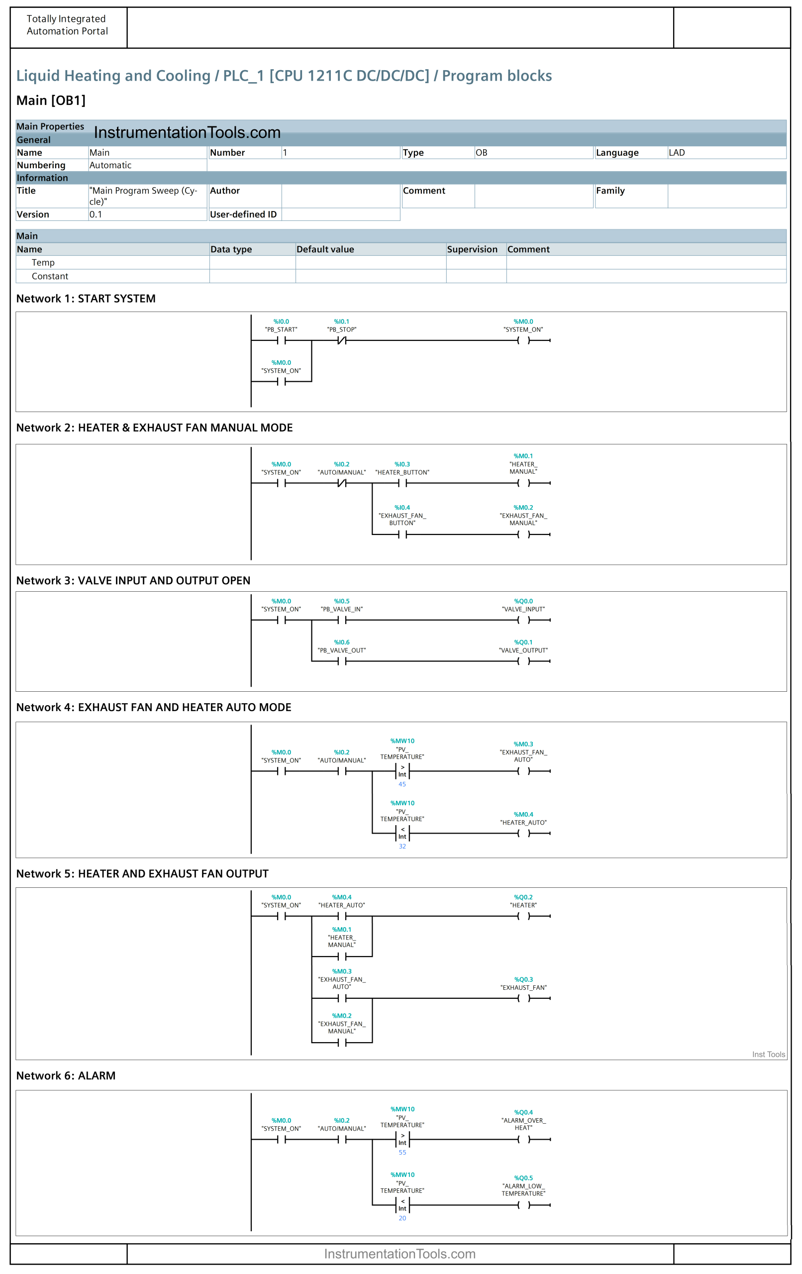
NETWORK 1 (START SYSTEM)
In this network, when the PB_START (I0.0) button is Pressed, the memory bit SYSTEM_ON (M0.0) will be in the HIGH state. Because it uses Latching, even though the PB_START (I0.0) button has been Released the memory bit SYSTEM_ON (M0.0) will remain in the HIGH state.
If the PB_STOP (I0.1) button is Pressed, the memory bit SYSTEM_ON (M0.0) will be in the LOW state.
NETWORK 2 (HEATER & EXHAUST FAN MANUAL MODE)
In this network, if the NO contact of the memory bit SYSTEM_ON (M0.0) in the HIGH state and the HEATER_BUTTON (I0.3) button is Pressed, then the memory bit HEATER_MANUAL (M0.1) will be in the HIGH state.
If the NO contact of the memory bit SYSTEM_ON (M0.0) in the HIGH state and the EXHAUST_FAN_BUTTON (I0.4) button is Pressed, then the memory bit EXHAUST_FAN_MANUAL (M0.2) will be in the HIGH state.
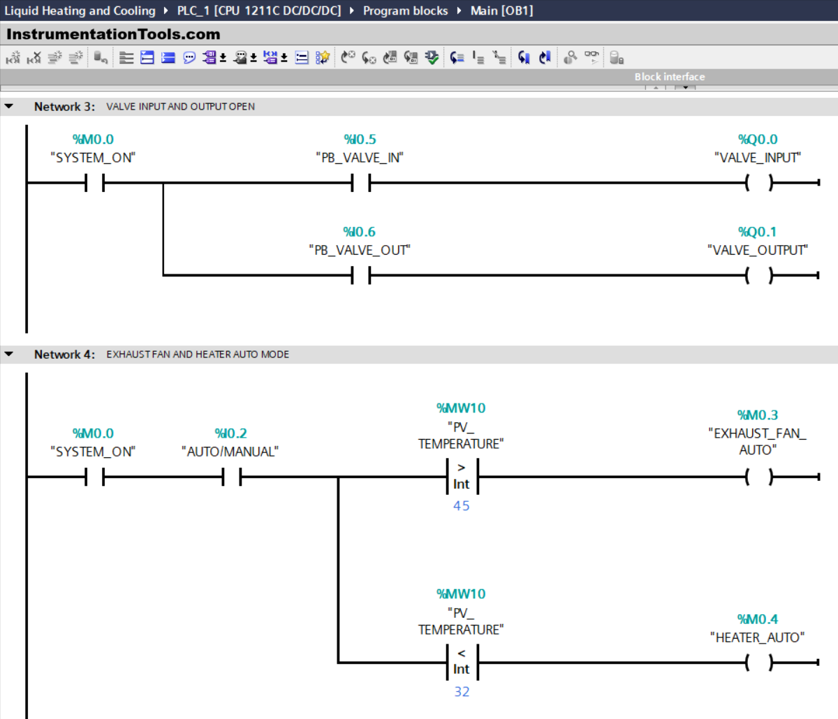
NETWORK 3 (VALVE INPUT AND OUTPUT OPEN)
In this network, when the NO contact of the memory bit SYSTEM_ON (M0.0) is in the HIGH state and the PB_VALVE_IN (I0.5) button is Pressed, the VALVE_INPUT (Q0.0) output will become OPEN.
When the NO contact of the memory bit SYSTEM_ON (M0.0) in the HIGH state and the PB_VALVE_OUT (I0.6) button is Pressed, the VALVE_OUTPUT (Q0.1) output will become OPEN.
NETWORK 4 (EXHAUST FAN AND HEATER AUTO MODE)
In this Network, when the NO contact of the memory bit SYSTEM_ON (M0.0) and Selector Switch AUTO/MANUAL (I0.2) in the HIGH state and the value in the memory word PV_TEMPERATURE (MW10) is Greater Than “45”, then the memory bit EXHAUST_FAN_AUTO (M0.3) will be in HIGH state.
When the NO contact of the memory bit SYSTEM_ON (M0.0) and the Selector Switch AUTO/MANUAL (I0.2) in the HIGH state and the value in the memory word PV_TEMPERATURE (MW10) is Less Than “32”, then the memory bit HEATER_AUTO (M0.4) ) will be in the HIGH state.
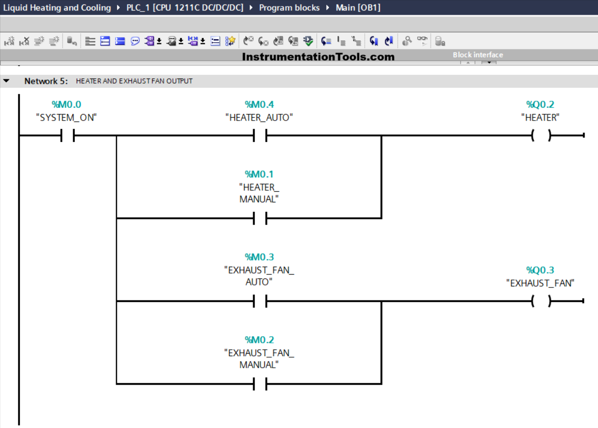
NETWORK 5 (HEATER AND EXHAUST FAN OUTPUT)
In this Network, if the NO contacts of the memory bits SYSTEM_ON (M0.0), HEATER_AUTO (M0.4), and HEATER_MANUAL (M0.1) are in the HIGH state, then the HEATER (Q0.2) output will be ON.
If the NO contacts of the memory bits SYSTEM_ON (M0.0), EXHAUST_FAN_AUTO (M0.3), and EXHAUST_FAN_MANUAL (M0.2) are in the HIGH state, then the output EXHAUST_FAN (Q0.3) will be ON.

NETWORK 6 (ALARM)
In this Network, when the NO contact of the memory bit SYSTEM_ON (M0.0) and the Selector Switch AUTO/MANUAL (I0.2) are in the HIGH state and the value in the memory word PV_TEMPERATURE (MW10) is Greater Than “55”, then the output is ALARM_OVER_HEAT (Q0.4) will be ON.
If the NO contact of the memory bit SYSTEM_ON (M0.0) and the Selector Switch AUTO/MANUAL (I0.2) are in the HIGH state and the value in the memory word PV_TEMPERATURE (MW10) is Less Than “20”, then the output ALARM_LOW_TEMPERATURE (Q0.5) will be ON.
Read Next:
- Electrical Motor Protection Circuits
- PLC Programming on Bottle Line Control
- Fish Farm PLC Automation Programming
- How Overload Heaters Shut the Motor OFF?
- Immersion Electrical Heaters Wiring Circuits