Inst ToolsInst ToolsInst Tools
  • Courses
  • Automation
    • PLC
    • Control System
    • Safety System
    • Communication
    • Fire & Gas System
  • Instrumentation
    • Design
    • Pressure
    • Temperature
    • Flow
    • Level
    • Vibration
    • Analyzer
    • Control Valve
    • Switch
    • Calibration
    • Erection & Commissioning
  • Interview
    • Instrumentation
    • Electrical
    • Electronics
    • Practical
  • Q&A
    • Instrumentation
    • Control System
    • Electrical
    • Electronics
    • Analog Electronics
    • Digital Electronics
    • Power Electronics
    • Microprocessor
Search
  • Books
  • Software
  • Projects
  • Process
  • Tools
  • Basics
  • Formula
  • Power Plant
  • Root Cause Analysis
  • Electrical Basics
  • Animation
  • Standards
  • 4-20 mA Course
  • Siemens PLC Course
Reading: Identify Level Control Loop Tuning Problems
Share
Notification Show More
Font ResizerAa
Inst ToolsInst Tools
Font ResizerAa
  • Courses
  • Design
  • PLC
  • Interview
  • Control System
Search
  • Courses
  • Automation
    • PLC
    • Control System
    • Safety System
    • Communication
    • Fire & Gas System
  • Instrumentation
    • Design
    • Pressure
    • Temperature
    • Flow
    • Level
    • Vibration
    • Analyzer
    • Control Valve
    • Switch
    • Calibration
    • Erection & Commissioning
  • Interview
    • Instrumentation
    • Electrical
    • Electronics
    • Practical
  • Q&A
    • Instrumentation
    • Control System
    • Electrical
    • Electronics
    • Analog Electronics
    • Digital Electronics
    • Power Electronics
    • Microprocessor
Follow US
All rights reserved. Reproduction in whole or in part without written permission is prohibited.
Inst Tools > Blog > Control Systems > Identify Level Control Loop Tuning Problems

Identify Level Control Loop Tuning Problems

Last updated: July 28, 2019 11:43 am
Editorial Staff
Control Systems Practical Questions
1 Comment
Share
2 Min Read
SHARE

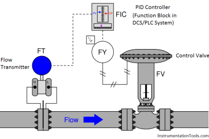
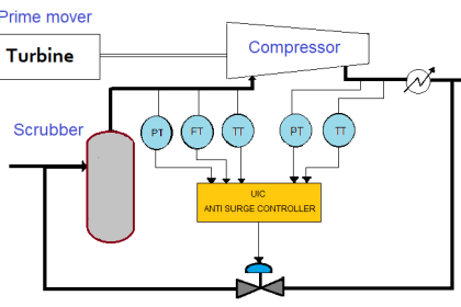
A level control loop is supposed to maintain a constant level of liquid at the bottom of the stripping tower where considerable amount of vibration exists, but it seems to have a problem:

Contents
Level Control LoopAnswer :

Here is what the trend recording from Level Transmitter looks like during the time an operator placed the controller in manual mode and then back to automatic mode:

Level Control Loop

Identify Level Control Loop Tuning Problems

A fellow engineer tells you he thinks the controller is over-tuned (having too much gain). The operator, who just did the manual-mode test, disagrees.
Based on the information seen in the trend, what do you think the source of the oscillation is, and how would you go about testing your hypothesis?

Answer :

This oscillation is clearly not the result of an over-tuned controller, because it persists even when the controller is in manual mode. The source must be coming from somewhere else in the process.

At this point in time, it would be a good thing to note the frequency of this oscillation, and begin searching for anything that could cause the level to go up and down at this frequency, or perhaps something that could “fool” level transmitter (LT) into thinking the level is oscillating at this frequency. If the frequency is relatively high, local machine vibration could be the cause of it.

This hypothesis makes a lot of sense, based on the fact that the controller’s action in automatic mode doesn’t seem to be correcting the oscillations at all: the oscillation amplitude seems to remain unchanged between automatic and manual modes.

This is what we might expect from a vibration-induced oscillation, where the frequency of the oscillation is much faster than the liquid level can possible change, and therefore faster than the level control system can physically compensate.

Share Your Comments …

Articles You May Like :

Control Loop Questions

Safety Instrumented Systems

4-20mA Loop Power Supply

Feedback Control Loop

PLC Automatic Irrigation

Don't Miss Our Updates
Be the first to get exclusive content straight to your email.
We promise not to spam you. You can unsubscribe at any time.
Invalid email address
You've successfully subscribed !

Continue Reading

Guided-wave Radar Asset Management Parameters
What is Interposing Relay in a PLC System ?
Runaway Processes
Difference between DCS, PLC, and RTU ?
Commissioning Documents for Instrumentation Engineers
Setpoints and Alarms in Control System
Share This Article
Facebook Whatsapp Whatsapp LinkedIn Copy Link
Share
1 Comment
  • Undefined says:
    April 9, 2019 at 12:11 pm

    how does the vibration can change the PV. @ i am having a flow transmitter which goes for 24 tph for 3 min and then comes to 21 tph , what could be the reason

    Reply

Leave a Reply Cancel reply

Your email address will not be published. Required fields are marked *

Stay Connected

128.3kFollowersLike
69.1kFollowersFollow
208kSubscribersSubscribe
38kFollowersFollow

Categories

Explore More

How much Pressure will Remote Seal Pressure Transmitter Indicate?
Demo of a SCADA Software – Level Control System
Power Supply Sizing for Industrial Automation Systems
Question on Analytical Controller
Does Really a Safety Barrier is Important? – PLC DCS Systems
Float-type Level Switch for Sensing Low Oil Level
Instrumentation and Electrical Teams Interactions (Detail Design Engineering)
4-20mA Loop Power Supply Questions and Answers

Keep Learning

Electrical and Instrumentation Engineering Documents

Electrical and Instrumentation – Automation Pre-engineering Documents

Boiler Intelligent Control Cabinet

IoT based Smart Boiler Control System with Cloud PLC and SCADA

What Effect on Hydrostatic Level Transmitter if Liquid Density Changes?

What Effect on Hydrostatic Level Transmitter if Liquid Density Changes?

Single-element drum level control system

Single Element Drum Level Control System

Field Instrument package

Package System Architecture – Control & Instrumentation

Supervisory Control

Supervisory Control

Heat Exchanger Outlet Temperature Control

Heat Exchanger Temperature Control

Identify which lamp in the following ladder-logic diagram

Identify High Flow Alarm and Low Flow Alarm?

Learn More

State Variable Analysis and Design

Controllability & Observability

Top 100 Instrumentation Engineering Questions & Answers

Top 100 Instrumentation Engineering Questions & Answers

Power Electronics Objective Questions

Harmonic Reduction Objective Questions

What is a K Factor

Flow Meter K-factor and Calculations

Temperature Measurement Interview

Temperature Measurement Interview Questions

Partial Stroke Testing Device (PSD) in SIS Final Control Element

Partial Stroke Testing Device (PSD) in SIS Final Control Element

Field Instruments Selection Aid

Field Instruments Selection Aid

Proximity Switch PNP Type Working Animation

Proximity switches Circuit Diagram Operation

Follow US
All rights reserved. Reproduction in whole or in part without written permission is prohibited.
Welcome Back!

Sign in to your account

Username or Email Address
Password

Lost your password?