The main goal of power system protection is to separate the faulty section of the system to ensure the remaining parts can continue to operate without any disturbances. Also, it is used to safeguard the power system by preventing the flow of fault current and quickly disconnecting the short circuits and damages.
With the fast growth of power systems and the integration of generators, and transformers, achieving a high degree of reliability has become more difficult now. We require protection devices like relays and circuit breakers to protect the system from possible damage caused by unusual conditions such as short circuits, undercurrents, and overcurrents. These protection systems also play a major role in detecting issues like overloads, under voltages, overvoltage, under frequency, power reversal, and system instability.
Functions of a Protection System
Reliability
A key requirement of protection relays is their reliability. Although they were continually inactive for a longer duration when the fault occurs they should respond immediately and at a quicker time, it should do all the processes for protecting the system from the damages.
Selectivity
Protection devices like relays do not need to be functioned at all times, they may need to remain inactive or they may respond after some delay as per the requirement. For this type of action, relays need to be capable of distinguishing the required conditions like when they need to do an operation or when they need to do the operation with a delay. So protection devices must operate only under the conditions for which they are designed.
Sensitivity
Protective equipment must be sensitive enough to detect and respond quickly when a fault condition slightly exceeds a predefined limit.
Speed
Protection relays must operate at the required speed to decrease the system problems. If more relays are connected in the system they should be correctly coordinated to ensure the fault in one part of the system should not affect the other good components.
Normal or Rated Current
It is the maximum current that an electrical device or machine can work continuously throughout its operational life. As long as the load current in the machine remains within the specified current rating, the temperature of all the components in the machine will stay within safe limits, which will provide good performance and reliability.
Faulty Circuit
A fault in an electrical circuit refers to a defect in the circuit that diverts current from its normal path. Normally, it occurs due to irregular conditions that make the insulation between phases and the earth or between two conductors and any earthed shielding around them weaker than normal.
These faults normally result in a high current flow or a decrease in impedance between conductors or between conductors and the earth, which reduces the normal operating value of the circuit from its normal level. These are the possible reasons for the irregular conditions for making the circuit faulty.
Switch Gear Units
Switchgear is the device used for safeguarding the electrical devices or components in the electrical power system from any abnormalities or uneven conditions. Usually, these switchgears consists controlling unit, metering unit and regulator unit which are used for controlling, metering and regulating the power to the electrical system. When these units area assembled in a logical sequence way means , they form a simple switch gear unit. Some of the examples of switch gear unit used in various operations are Circuit Breakers, fuses and isolators.
Fuse
In electronics and electrical engineering, a fuse is a low-resistance component that serves as a sacrificial device to protect circuits and source units/components from overcurrent. The major component of a fuse is a metal wire or strip that melts when excessive current flows through it, which will break the circuit connection and make the circuit open and if the circuit is open, the current will not flow to the components, thus it will be prevented from damage.
Basically over current is caused by short circuits, overloading, mismatched loads, or device failures. Fuses are the alternative component for circuit breakers which are commonly used in low-power and low-voltage applications. Unlike circuit breakers, a fuse must be replaced or rewired after it operates because if it is operated, it will melt. So it needs to be replaced with other strips.
In normal conditions, when the current rate is normal and within the safe limit, the heat generated in the fuse will be dissipated normally in the working system environment and the temperature on the fuse will be below the melting point of the strip. But whenever any short circuit or overcurrent occurs, the generation of the heat will be greater which causes the melting of the fuse strip, so it makes the circuit to open and it will prevent damage to the device or component from the overcurrent flow.
Types of Fuses
In an AC supply, the fuse is generally made up of a metal fuse element, a pair or set of contacts, and the body frame to support insulation. Based on the voltage levels fuses are classified into two categories.
Low voltage Fuse
Low voltage fuses are used in the area of lower current rating area whereas consumption of voltage will be lower. These low voltage fuses are further classified into semi-closed fuse and cartridge fuse. In this semi-closed fuses are used in domestic wiring and small power applications.
The cartridge fuse has a sealed design with an equipped fuse base and a screw-on cap. The circuit will be in closed condition only when the cartridge tip makes contact with the conductor. Out of these two cartridge fuses are highly reliable.
High Voltage fuse
High voltage fuses are used in power systems where the operating voltage is up to 115kV. They are commonly used for protecting instrument transformers, and electricity meters where the voltage fluctuation is high.
Usage of fuse
In many electrical applications, the current flowing through the system may fluctuate which may cause the system to fail, sometimes resulting in fire or severe damage. So the main purpose of the fuse is to protect the system from excessive current, over-voltage, or overheating.
Isolator
The isolator is nothing but a mechanical protective switch that is used to disconnect a particular part of an electrical circuit from the electrical system to prevent damage whenever required. This is usually operated in manual mode.
The isolator ensures a safe procedure while disconnecting the particular section from the active power system. Usually, isolators operate in a no-load condition to safely disconnect the circuit
Function of Electrical Isolator
These isolators do not have an arc-quenching mechanism, which means they must only be operated when no current is passing through the system. If we use an isolator for opening or closing a live circuit, it will produce a severe arcing which may lead to damage to the entire equipment. We can open the isolator if the circuit breaker is open and we can close the isolator if the circuit breaker is closed.
Usually, these Isolators are operated manually, but sometimes motorized mechanisms also be used. We can use manual isolators up to 145kV while motorized Isolators are used for high voltage systems exceeding 200kV. But Motorized operation was more expensive than manual.
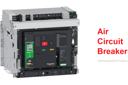
Circuit Breaker
A circuit breaker is also an electrical protection switch that is used to safeguard electrical circuits from problems like overcurrent, overloads, short circuits, etc., Its main function is to stop the flow of current whenever the fault is detected in the electrical system. During any faulty situation, it will automatically trip and cut the contact of the conductor and other systems.
The major advantage of the Circuit breaker while comparing the fuse was, that in the circuit breaker, we can reset to normal operation by using switching it to ON mode. But in Fuse, we need to replace the fuse element. These circuit breakers come in various sizes, ranges, and modes for household applications to large power systems.
Arc interruption in Circuit Breaker
In a circuit breaker, when a short circuit occurs, a large current will be flown through its contacts. At that time, these contacts begin to separate in response to the fault, so that the contact area decreases quickly. So there will be high current density which causes the rise in heat on that medium of point of contact. Thus the medium becomes conductive which forms an arc between the contacts.
During that time, the potential difference between the fixed and moving contacts was small which would just sustain the arc. Then the arc creates a low resistance path for the current, preventing the break of current flow. During the arcing period, the current passing through the circuit breaker mostly depends on the resistance of the arc. If the arc resistance is higher, it will reduce the current flow through the contacts of the circuit breaker.
Following are the factors that affect the arc resistance.
- If there is higher ionization on the contact medium, it will lower the arc resistance
- During arcing, if the distance between the contacts increases means, the length of the arc will also increase which leads to an increase in arc resistance
- During arcing, cross cross-sectional area of the arc is smaller means then the arcing resistance will be higher.
Principle of Arc Extinction in Circuit Breaker
The insulation material used in the circuit breaker needs to havethe following two important functions.
They are:
- It should provide suitable insulation for isolating the contacts when the circuit breaker is in open condition
- During the contact opening process in the circuit breaker, it needs to extinguish the arc.
Arc Voltage
Arc voltage is the voltage that occurs across the circuit breaker contacts during the arcing period. Its value is typically low but it will spike to its peak when the produced arc current reaches zero, attempting to withstand the arc between the contacts of the circuit breaker
Restriking Voltage
Restriking voltage is the voltage that occurs across the circuit breaker contacts immediately after they are turned on. This will give a high frequency voltage which was caused by a sudden distribution of energy between the electric and magnetic field during the current across the contact of the circuit breaker is zero.
Recovery Voltage
Recovery voltage is the steady-state RMS system voltage that will appear in the system across the circuit breaker contacts only when the arc has been completely extinguished
Conclusion
In this, we have discussed some of the protective systems for the electrical systems. These protective systems play an important part in safeguarding the generation, transmission, and distribution of power with minimum interruptions and fast restoration times. The importance of protective equipment in the system is it helps to reduce the impact of faults that could otherwise cause heavy damage to the entire system.
Read Next:
- Automatic Circuit Recloser
- De-energized Electrical Circuits
- How to Locate Faults in Cables?
- Variable Air Volume Controller
- Why is HV Testing important?