Inst ToolsInst ToolsInst Tools
  • Courses
  • Automation
    • PLC
    • Control System
    • Safety System
    • Communication
    • Fire & Gas System
  • Instrumentation
    • Design
    • Pressure
    • Temperature
    • Flow
    • Level
    • Vibration
    • Analyzer
    • Control Valve
    • Switch
    • Calibration
    • Erection & Commissioning
  • Interview
    • Instrumentation
    • Electrical
    • Electronics
    • Practical
  • Q&A
    • Instrumentation
    • Control System
    • Electrical
    • Electronics
    • Analog Electronics
    • Digital Electronics
    • Power Electronics
    • Microprocessor
Search
  • Books
  • Software
  • Projects
  • Process
  • Tools
  • Basics
  • Formula
  • Power Plant
  • Root Cause Analysis
  • Electrical Basics
  • Animation
  • Standards
  • 4-20 mA Course
  • Siemens PLC Course
Reading: Introduction to Functional Block Diagram in Studio 5000
Share
Notification Show More
Font ResizerAa
Inst ToolsInst Tools
Font ResizerAa
  • Courses
  • Design
  • PLC
  • Interview
  • Control System
Search
  • Courses
  • Automation
    • PLC
    • Control System
    • Safety System
    • Communication
    • Fire & Gas System
  • Instrumentation
    • Design
    • Pressure
    • Temperature
    • Flow
    • Level
    • Vibration
    • Analyzer
    • Control Valve
    • Switch
    • Calibration
    • Erection & Commissioning
  • Interview
    • Instrumentation
    • Electrical
    • Electronics
    • Practical
  • Q&A
    • Instrumentation
    • Control System
    • Electrical
    • Electronics
    • Analog Electronics
    • Digital Electronics
    • Power Electronics
    • Microprocessor
Follow US
All rights reserved. Reproduction in whole or in part without written permission is prohibited.
Inst Tools > Blog > PLC Tutorials > Introduction to Functional Block Diagram in Studio 5000

Introduction to Functional Block Diagram in Studio 5000

Discover the advantages of using the Introduction to Functional Block Diagram in Studio 5000 for advanced PLC programming.

Last updated: April 1, 2025 10:09 am
Viral Nagda
PLC Tutorials
No Comments
Share
5 Min Read
SHARE

Functional block diagram is a language that is very popular in PLC programming, for the various advantages it provides. Its high graphical representation and advanced diagnostics prove as a very handy tool for PLC programmers.

Contents
Introduction to Functional Block DiagramStudio 5000

Introduction to Functional Block Diagram

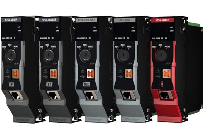
One of the most popular platforms in industrial automation is Rockwell Automation. The software used in it, Studio 5000, is a very advanced software for PLC programmers. The functional block diagram is present in this software too. We will start a series of this language used in Studio 5000. Starting with the first post here, we will see a brief introduction and overview of the functional block diagram in Studio 5000.

Functional block diagram is available for programmingin Studio 5000. Whenever you want to design a logic in this language, you will select a functional block diagram from the options and then you can work on it.

Studio 5000

Let us have a look at some introductory features of this language in Studio 5000:

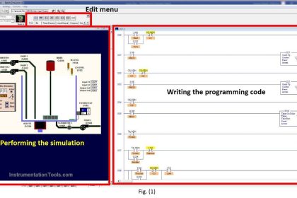
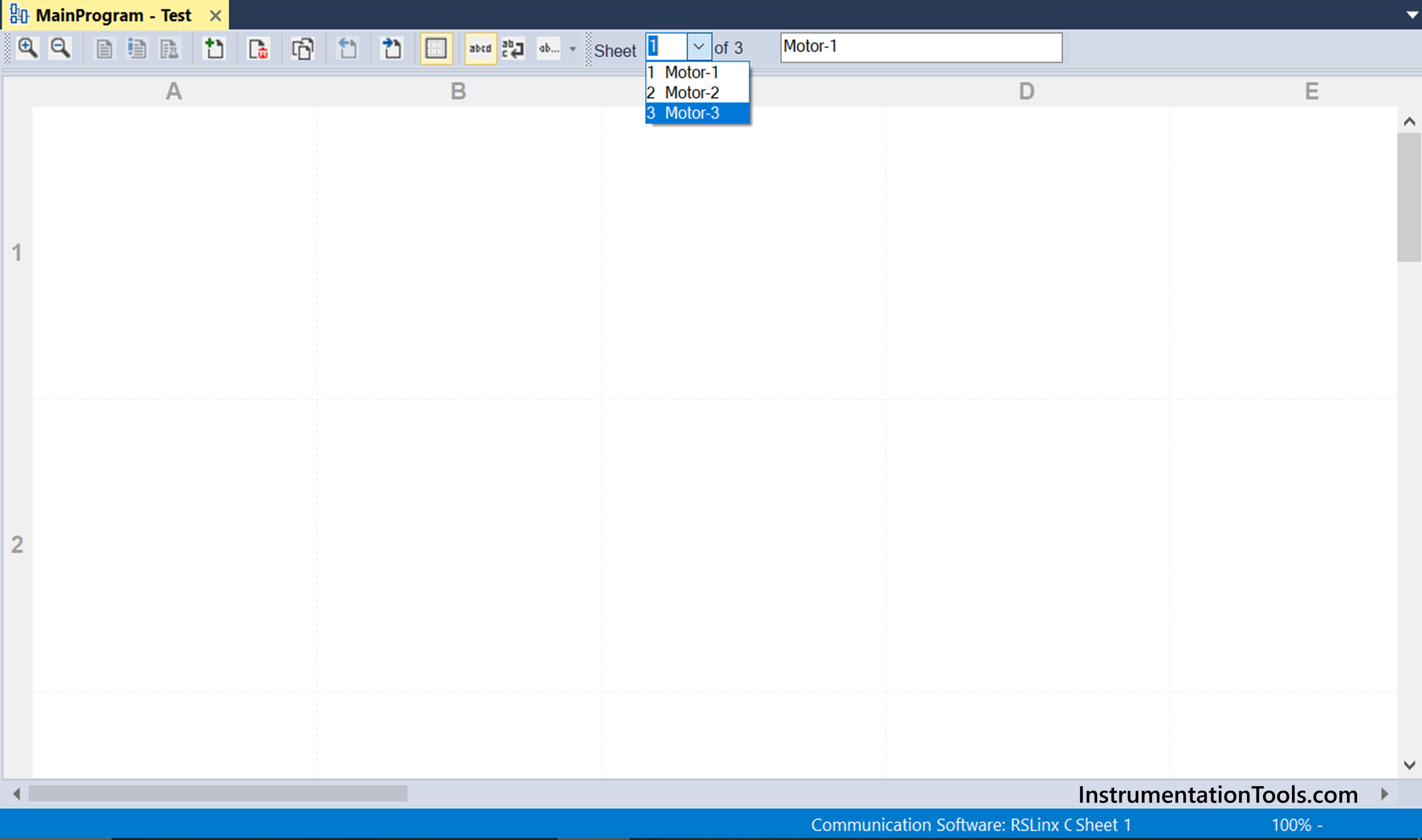
  1. You can organize sheets in a single routine. This feature is available only in Rockwell automation. This means, suppose you write a routine named motor logic. There are 12 such motors, each having the same or interrelated logic. Instead of writing 12 different routines or sections, write a single section. In that section, use 12 different sheets. This will help to minimize the program view and also simplify troubleshooting for programmers. They make the logic easier to locate and use. Refer to the below image for a general understanding.
Introduction to Functional Block Diagram in Studio 5000
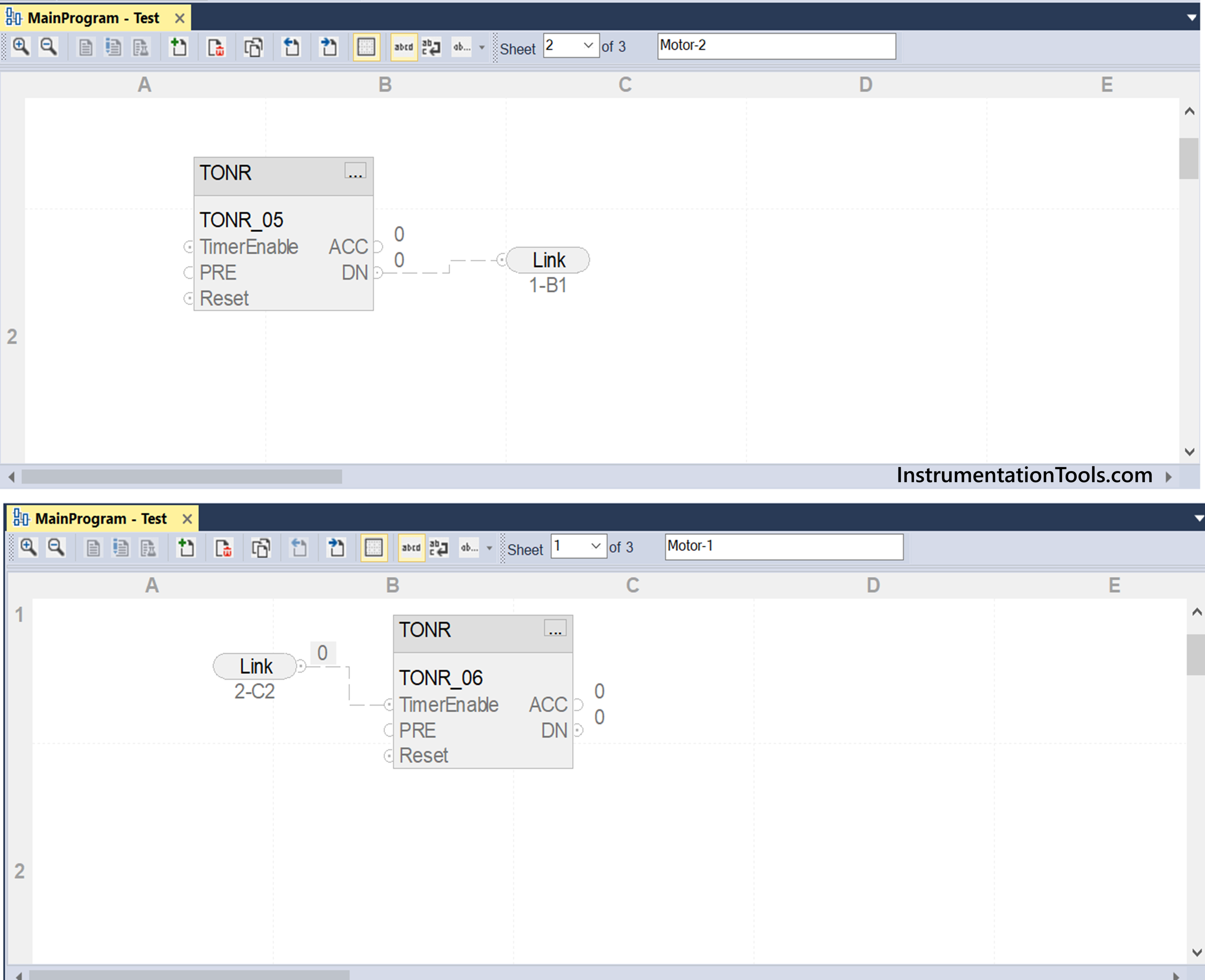
  1. As sheets are provided, this software provides one interesting feature to interlink the sheets – a wire connector. You can link internal tags here, which will not be used by PLC CPU execution. These tags are solely used for interlinking sheets. This means suppose there are 2 sheets. You want to link the output of a block in the first sheet to the input of a block in the second sheet. Instead of creating variables or dynamic linking of block outputs, you can create local variables which will only be used in wire connectors for linking a sheet. These variables will not be written any value by PLC, but just be used for navigating. Refer to the below image for more information. Here, you can see that the timer output in sheet-2 is linked to a timer input in sheet-1 using a tag called link. This tag is static and not written by PLC, but merely used for navigating to a sheet (you can see the link as 1-B1 or 2-C2, with the number denoting sheet number and alphabet denoting object positioning).
Function Block Programming in Studio 5000
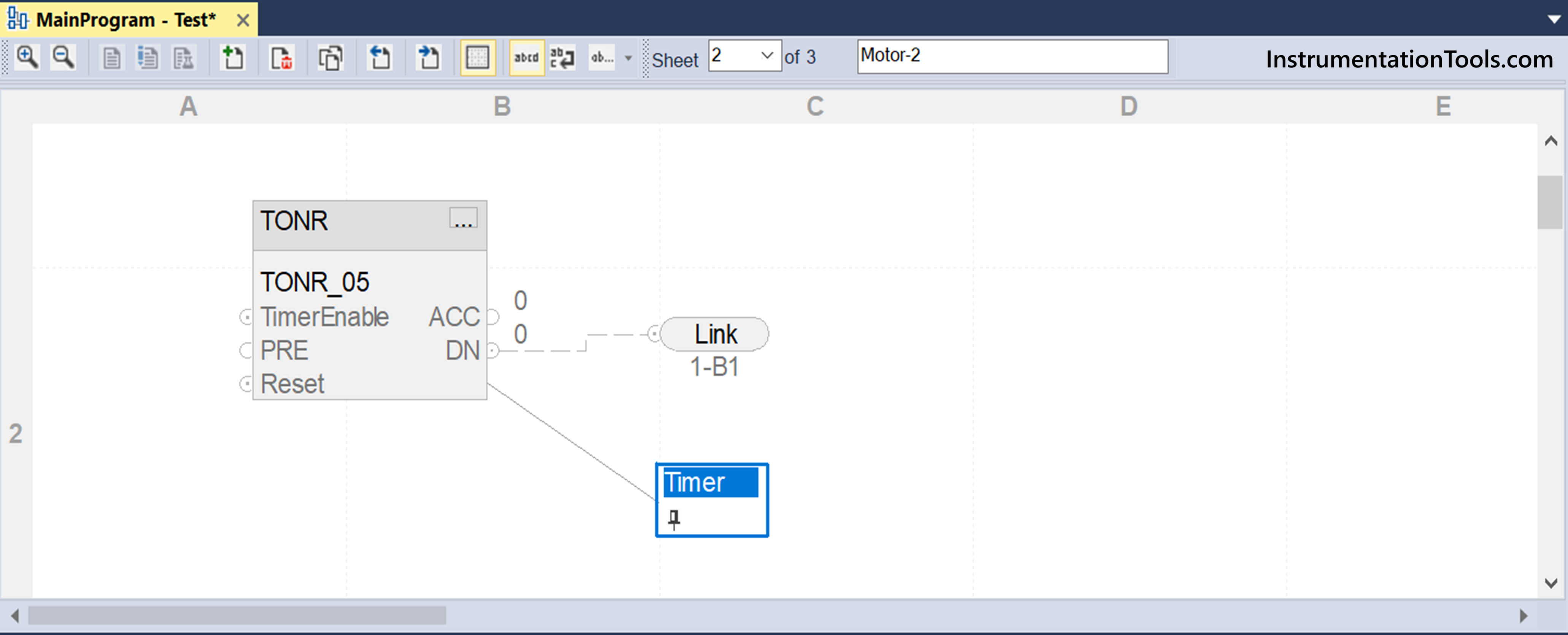
  1. You can assign a text box, which is nothing but a comment. Then, you have the option of attaching this text box to an object in the program. This indicates the use of the object in the program. Refer to the below image. Here, a text box named timer is attached to the timer in the program. It is just an indication or comment for the same.
Studio 5000 FBD Intro
  1. You can draw block diagrams as usual and link them to represent a proper block diagram. If you are falling short in building and linking blocks, then you can change the sheet size from letter to A0, in the sheet layout option.
  2. Apart from that, all the available blocks in the software can be used and placed in this language.

In this way, we saw a brief introduction to functional block diagrams in Studio 5000. In the next post, we will see how to define the order of execution with an example.

Read Next:

  • Motor Control Signal Interface Theory
  • Highway Lights Program using RTC in PLC
  • Product Sticker Machine PLC Programming
  • PLC Programming for Digital Alarms System
  • PLC Product Painting with Weighing System
Don't Miss Our Updates
Be the first to get exclusive content straight to your email.
We promise not to spam you. You can unsubscribe at any time.
Invalid email address
You've successfully subscribed !

Continue Reading

PLC Timer Application in Security Camera Recording
PLC Program for Automatic Mixing Control in a Tank
SCADA Software and their Comparison
Download Free HMI software – CODESYS
How to Use Symbol Factory Software for Graphic Design in HMI or SCADA?
Distributed IO Sharing Between PLC Systems – Technical Insights
Share This Article
Facebook Whatsapp Whatsapp LinkedIn Copy Link
Share
Leave a Comment

Leave a Reply Cancel reply

Your email address will not be published. Required fields are marked *

Stay Connected

128.3kFollowersLike
69.1kFollowersFollow
210kSubscribersSubscribe
38kFollowersFollow

Categories

Explore More

PLC Program for Blinking Lamp on 5 Seconds Interval
PLC Alarm and Trip Documentation
How is Data Stored in Standard Modbus Protocol?
PLC Programming for Sequential Batch Mixing System
PLC Mixing Logic in Liquids on EcoStruxure Machine Expert-Basic
Studio 5000: Define Program or Operator Control in Functional Block Diagram
Establish Communication Between Two PLC Via PROFIBUS Protocol
What is Trace Function in Tia Portal?

Keep Learning

Top PLC Manufacturers

PLC Brands Software Information

PLC Latched Circuit Example

PLC Latching Function

Auto Sugar Bag Filling Station

Auto Sugar Bag Filling Station

PLC Program for an Alternate output circuit

PLC Program for Alternate Output Circuit with Latched Function

Mixing Tank Relay Circuit

PLC Program for Mixing Tank

How to Choose HMI

How to Choose a Suitable HMI for Your Application?

PLC to Start or Stop 3 Machines using 1 Switch Program

PLC to Start or Stop 3 Machines using 1 Switch Program

Surface Grinding Process using PLC Program

Surface Grinding Process using PLC Program

Learn More

Control Valves Questions and Answers

Control Valve Questions and Answers

Transmitter Performance and Calibration Frequency

How to Calculate Transmitter Performance and Calibration Frequency?

Ethernet Questions and Answers

Ethernet Communication Interview Questions & Answers

Pressure Transmitter Circuit

Pressure Transmitter Circuit

Convert Raw Counts to Engineering Units

Raw Counts to Engineering Units : Conversion Formula

Electro Chemical Transducers Objective Questions

Electro Chemical Transducers Objective Questions

Why Starting Current of Induction Motor is High

explosion-proof electrical enclosures

Classified Areas and Electrical Safety Measures

Menu

  • About
  • Privacy Policy
  • Copyright

Quick Links

  • Learn PLC
  • Helping Hand
  • Part Time Job

YouTube Subscribe

Follow US
All rights reserved. Reproduction in whole or in part without written permission is prohibited.
Welcome Back!

Sign in to your account

Username or Email Address
Password

Lost your password?