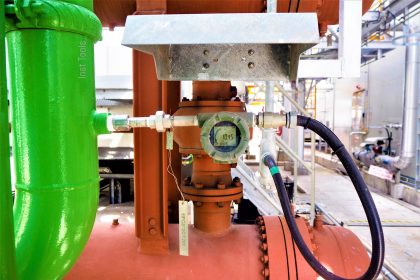
The instrument air compressor type that usually used in the offshore applications is a screw rotary type. This type is used due to its large flow capacity and relatively low discharge pressure but still more than enough to supply instrument equipment or any other utilities needed.
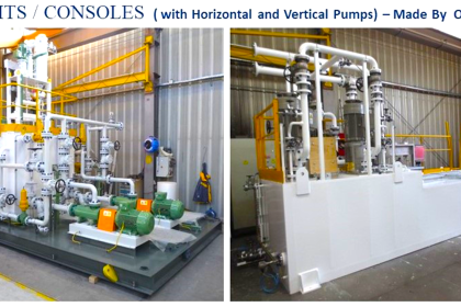
Instrument Air Compressor

Image courtesy: airmac
Since the instrument air compressor didn’t constantly supply a certain flow, thus it needs some control scheme in order to operate the instrument air compressor efficiently. There are on-off or start/stop control, load/unload control, and also variable speed control.
On-Off or Start/Stop Control
This is the basic instrument air compressor control. This control scheme is just simply turns off the compressor when the pressure in the instrument air network reaches a certain high level and turns on when the pressure goes down below the set pressure.
This control scheme is effectively used when the continuous demand of the compressed air is less than 50% of the compressor capacity. This type of control scheme usually also limited to a small compressor size only (below 10Hp).
The disadvantage of this control scheme is that too frequent start/stop cycle will make a bearing part worn down.
Load/Unload Control
This load/unload control scheme is utilizing a load/unload valve. When the pressure in the instrument air network reach a high set pressure, the load/unload valve will close but there are still certain small intake volume goes through the flow restriction.
At the same time, the discharge of the compressor bleeds out to the atmosphere through a vent valve. In this way, the compressor will operate on atmospheric pressure only and reduce power consumption.
This control scheme is also completed with a timer so that after several minutes the compressor was unloading, the motor with also shutting down by the controller. This is the most used control scheme for a large number of instrument air users in the instrument air network.
By applying this control scheme, instead of having a frequent start/stop it will have an unload condition for a certain time (can 30 minutes or more). If after a certain time it still unloads, then it will surely off the motor.
Variable Speed Control
This variable speed control scheme is utilizing a variable frequency drive as a motor controller. When the load in the instrument air network is low, then the pressure transmitter will indicate this and send a process variable to the Variable Frequency Drive (VFD).
This VFD will adjust the motor speed to adjust the compressor compression speed. Thus the compressor capacity will go down following the low demand on the instrument air network.
When the load is high, the pressure in the instrument air network will be down and the pressure transmitter will send this signal to the VFD.
Once again the VFD will adjust the motor speed so that the compressor capacity is increasing. This control scheme is the most precise control of the compressor but having an initial high installation cost.
Which control scheme we must use?
As a default, for a large Central Processing Platform or a Refinery Plant application, the load/unload control scheme can be selected as a preliminary control scheme.
The on-off control scheme can be selected for a small use only while the variable speed control scheme can be selected after some cost comparison calculation with the load/unload control scheme.
Share Your Plant instrument Air Compressor details with us.
Read Next:
Calculations of Instrument Air
What is Instrument Air Manifold ?


ELGI AIR COMPRESSORES WITH LOAD UNLOAD CONTROL SCHEMES.
Thank you for sharing knowledge.