Designing industrial automation is a very detailed engineering task, as it involves knowledge of electronics, electrical and instrumentation control. As it involves so many departments, it will thus require strong documentation to fulfill it.
Documentation is always the first step in successfully executing a project. If the documents are proper, then the concerned persons involved can properly execute the task.
Industrial automation has many design documents related to pre-engineering (before starting and finalizing the project).
Industrial Automation Pre-Engineering Documents
In this post, we will have a look at the various pre-engineering design documents related to industrial automation, which are necessary to finalize a project. This post is divided into two parts, as it is lengthy and cannot be covered in one topic. We will see the first part which deals with the project and process. You can read the second part related to electrical and instrumentation engineering documents.
Document Control Index
The Document Control Index is one of the main documents in preparing a project. It is a way of linking all digital documents with some attributes or labels.
Simply say, if you have “n” number of document parts. You don’t know which document is related to which subject and what is its meaning. So, this index will be used in every document to help it identify the type and its purpose.
Document Control Index document makes discovering files easier and so allows the user to access any document at any moment with a few clicks. If you have done proper indexing, then you can properly arrange them in sub-folders according to their category.
A simple example will be tagging a document based on the client name, consultant name, date, purchase order number, and its heading title (which means the type of document). When you are designing a project, this index is a must in pointing to various types and meanings of them.
Material Control Index
You are giving materials in a project and if you have no control over it, then the project is a waste of time. Material control index is a special type of document which helps in dealing with it. It starts from procurement and goes till the last usage stage.
Material Control Index document includes purchasing or procurement of materials, receiving of materials, an inspection of materials, storage of materials, issuing of materials, maintenance of material records and materials, or stock audit.
If you have a proper idea of this, then only you commit a customer how long a project will take to complete. This will also help in the following things – uninterrupted protection by continuous availability, minimum wastage and loss of materials, financial control, less delay in production, and high-quality assurance and efficiency. This document must be available in hand before taking on any project.
Project Schedule
You must maintain proper dates with the customer in the completion of a project. Every project has many stages – like machine design, material management, GA approval, electrical drawings submission, and approval, commissioning team manpower timelines, electrical panel manufacturing, software development, FAT, and dispatch.
If the dates are approximately decided between you and the customer, it will help in the proper and timely execution of a project.
Every project stage must be completed within the set time, which will eventually help finish the project. So, it is important to maintain the project schedule with the customer before taking the order in hand.
Commissioning Schedule
When you have decided on the project schedule, it is necessary to share the commissioning schedule with the customer.
The commissioning Schedule document will contain information regarding the project completion date, material receive at the site, commissioning team arrival dates, pre-commissioning activities start (utility, electrical and mechanical), actual commissioning activities start with process start-up, and operational readiness.
Though these dates are not always actual, they have to be met tentatively which will help in a successful completion.
P and ID Diagram
P & ID stands for pipeline and instrumentation diagram. Basically, this drawing gives you an overall look at detailed piping, instrument location, tank location, utility transfer source and destination, and construction process.
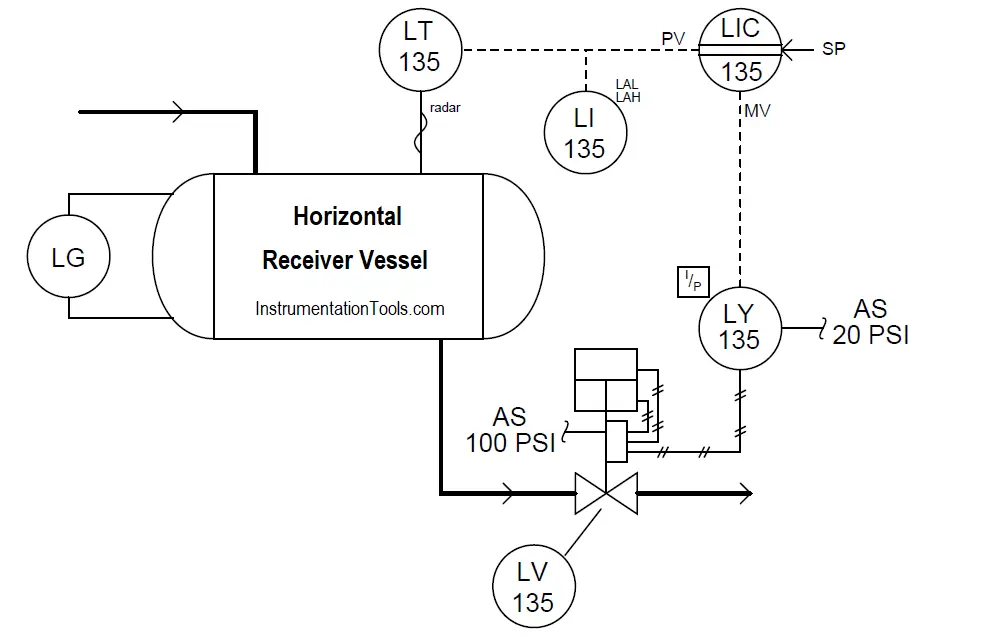
After understanding client requirements and conveying your possibilities, you design the P and ID. This document will then help to understand how the process will look like, flow, and complete. P&ID is also a very important document for programmers to understand process flow, which will help them to design the program accordingly.
Process Flow Diagram
Process Flow Diagram can be termed as the parent of the P and ID diagrams. Actually, on the basis of this diagram, the P and ID diagram is designed.
Simple, consider you have five processes in a plant. If you know how a process will flow from start to end, then you can easily design the system accordingly. It is a type of flowchart that illustrates the relationships between major components at an industrial plant. They use a series of symbols and notations to depict a process.
The symbols vary in different places, and the diagrams may range from simple, hand-drawn scrawls or sticky notes to professional-looking diagrams with expandable detail, produced with software.
These are some general project and process documents required. In the next post, we will see the documents related to electrical, instrumentation, and ITP. In this way, we saw the pre-engineering design documents related to industrial automation (projects and process).
If you liked this article, then please subscribe to our YouTube Channel for Instrumentation, Electrical, PLC, and SCADA video tutorials.
You can also follow us on Facebook and Twitter to receive daily updates.
Read Next:
- What are FAT and SAT?
- Instrumentation Problems
- Instrument Numbering Philosophy
- How to Fill up Instrument Datasheet?
- Tagging Philosophy for Junction Box