Inst ToolsInst ToolsInst Tools
  • Courses
  • Automation
    • PLC
    • Control System
    • Safety System
    • Communication
    • Fire & Gas System
  • Instrumentation
    • Design
    • Pressure
    • Temperature
    • Flow
    • Level
    • Vibration
    • Analyzer
    • Control Valve
    • Switch
    • Calibration
    • Erection & Commissioning
  • Interview
    • Instrumentation
    • Electrical
    • Electronics
    • Practical
  • Q&A
    • Instrumentation
    • Control System
    • Electrical
    • Electronics
    • Analog Electronics
    • Digital Electronics
    • Power Electronics
    • Microprocessor
  • Request
Search
  • Books
  • Software
  • Projects
  • Process
  • Tools
  • Basics
  • Formula
  • Power Plant
  • Root Cause Analysis
  • Electrical Basics
  • Animation
  • Standards
  • 4-20 mA Course
  • Siemens PLC Course
Reading: Impulse Line Pressure Testing Procedure
Share
Font ResizerAa
Inst ToolsInst Tools
Font ResizerAa
  • Courses
  • Design
  • PLC
  • Interview
  • Control System
Search
  • Courses
  • Automation
    • PLC
    • Control System
    • Safety System
    • Communication
    • Fire & Gas System
  • Instrumentation
    • Design
    • Pressure
    • Temperature
    • Flow
    • Level
    • Vibration
    • Analyzer
    • Control Valve
    • Switch
    • Calibration
    • Erection & Commissioning
  • Interview
    • Instrumentation
    • Electrical
    • Electronics
    • Practical
  • Q&A
    • Instrumentation
    • Control System
    • Electrical
    • Electronics
    • Analog Electronics
    • Digital Electronics
    • Power Electronics
    • Microprocessor
  • Request
Follow US
All rights reserved. Reproduction in whole or in part without written permission is prohibited.
Inst Tools > Blog > Calibration > Impulse Line Pressure Testing Procedure

Impulse Line Pressure Testing Procedure

Learn the testing procedure for the field instruments impulse line, pipe or tubing pressure leak test.

Last updated: October 17, 2023 2:13 pm
Editorial Staff
Calibration Pressure Measurement
No Comments
Share
2 Min Read
SHARE

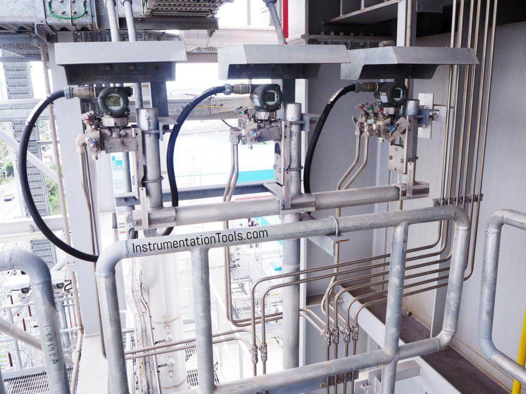
Learn the testing procedure for the field instruments impulse line, pipe, or tubing pressure leak test.

Contents
Test Pressure EquipmentTest MediumTesting PressureChecks To Be Carried Out Before Starting Pressure TestImpulse Line Testing ProcedurePost Testing ProcedureFinal Checks to be Carried Out
Impulse Line Pressure Testing Procedure

Test Pressure Equipment

  • Test gauge, Hydro manual pump, Hose
  • Guage used shall be calibrated +/- 1% accuracy and shall have valid calibrate stickers

Test Medium

  • Clean water
  • Air

Testing Pressure

  • The test pressure equipment shall be 1.5 times of the max. working pressure
  • Incase of pneumatic test, test pressure shall be 1.1 times

Checks To Be Carried Out Before Starting Pressure Test

  • Ensure that ferrules are correctly installed
  • Impulse lines shall be supported and slope maintained properly
  • Ensure that instrument connected is isolated
  • Barricade the area for hydro test access shall restrict to authorized persons only
  • Use all safety PPE’s ( Personal Protective Equipments)

Impulse Line Testing Procedure

  • After verifying the completeness of all above applicable records line shall be cleared for the pressure test
  • Avoid air pocket for mention vents at high points shall be left open and not closed until clean test medium flow from the outlet
  • If leaks are observed in the line, marks these leaks and de-pressurize the line
  • Before starting repairs, ensure that the lines shall be drained properly
  • If any repairs have been carried out, this line shall be re-pressurize tested, and documented

Post Testing Procedure

  • De-pressurization of the line shall be carried out in a controlled manner
  • Immediately release of pressure is not permitted
  • These lines are to be drained out and air flushed after testing

Final Checks to be Carried Out

  • All the tubes are to be properly cleaned by using compressed air
  • Check that all connections are done properly.

Read Next:
  • PLC Multiple Choice Questions
  • Flow Meter Questions and Answers
  • Impulse Piping standards for Field instruments
  • SIS Final Control Elements
  • Capacitance Level Switch Working Principle
Don't Miss Our Updates
Be the first to get exclusive content straight to your email.
We promise not to spam you. You can unsubscribe at any time.
Invalid email address
You've successfully subscribed !

Continue Reading

Practical Calibration Standards
Fine Wire Strain Gauge Principle
How Measurement Span of Pressure Gauge Could be Changed?
Differential Pressure Transmitter Questions
Stability and Uniformity of Temperature Bath
How to Test a Pressure Gauge
Share This Article
Facebook Whatsapp Whatsapp LinkedIn Copy Link
Share
Leave a Comment

Leave a Reply Cancel reply

Your email address will not be published. Required fields are marked *

Stay Connected

128.3kFollowersLike
69.1kFollowersFollow
210kSubscribersSubscribe
38kFollowersFollow

Categories

Explore More

How to Read Gauge Analog Scales
Bently Nevada Vibration Probes Functional Testing
Calibration of Pyrometers using Black Body
Pressure Transmitters Filled impulse lines
Double Block and Bleed Valves Opening or Closing Sequence
Pressure Gauge Installation at Pump Discharge
DP Transmitter Block and Bleed Valves
Automated Calibration

Keep Learning

DP Diaphragm Capillary Seal Level instrument

DP Diaphragm Capillary Seal Level instrument Calibration Procedure

Calibration of a Strain Gage Load Cell

Shunt Calibration of a Strain Gauge Load Cell

Instrument Turndown Ratio

Instrument Turndown Ratio

Multiple Position Calibration of Temperature Chamber (Mapping)

Multiple Position Calibration of Temperature Chamber

RTD Testing Methods

RTD Testing Methods in Calibration Laboratory

Calibration & Preventative Maintenance Procedures

Calibration and Preventative Maintenance Procedures

Displacer Level Transmitter weight calibration

Displacer Level Transmitter Dry Calibration with Weights

Strain gage load cells

Load Cell Healthiness Checks

Learn More

If Else Statement in SCL Language

If Else Statement in SCL Language

Protection Relays Interview Questions & Answers

Protection Relays Interview Questions & Answers

Power Systems Questions & Answers

Power Systems MCQ Series 22

Tilt Level Switch Theory

Tilt Level Switch Working Principle

Studio 5000 Logix Emulate

Simulation of Studio 5000 and FactoryTalk View Studio

Control Valves Flow Direction

Control Valve Flow Direction

AC Circuits Multiple Choice Questions

HART Communication Interview Questions

HART Communication Interview Questions and Answers

Menu

  • About
  • Privacy Policy
  • Copyright

Quick Links

  • Learn PLC
  • Helping Hand
  • Part Time Job

YouTube Subscribe

Follow US
All rights reserved. Reproduction in whole or in part without written permission is prohibited.
Welcome Back!

Sign in to your account

Username or Email Address
Password

Lost your password?