Inst ToolsInst ToolsInst Tools
  • Courses
  • Automation
    • PLC
    • Control System
    • Safety System
    • Communication
    • Fire & Gas System
  • Instrumentation
    • Design
    • Pressure
    • Temperature
    • Flow
    • Level
    • Vibration
    • Analyzer
    • Control Valve
    • Switch
    • Calibration
    • Erection & Commissioning
  • Interview
    • Instrumentation
    • Electrical
    • Electronics
    • Practical
  • Q&A
    • Instrumentation
    • Control System
    • Electrical
    • Electronics
    • Analog Electronics
    • Digital Electronics
    • Power Electronics
    • Microprocessor
Search
  • Books
  • Software
  • Projects
  • Process
  • Tools
  • Basics
  • Formula
  • Power Plant
  • Root Cause Analysis
  • Electrical Basics
  • Animation
  • Standards
  • 4-20 mA Course
  • Siemens PLC Course
Reading: Identify all Spool Valve Positions
Share
Notification Show More
Font ResizerAa
Inst ToolsInst Tools
Font ResizerAa
  • Courses
  • Design
  • PLC
  • Interview
  • Control System
Search
  • Courses
  • Automation
    • PLC
    • Control System
    • Safety System
    • Communication
    • Fire & Gas System
  • Instrumentation
    • Design
    • Pressure
    • Temperature
    • Flow
    • Level
    • Vibration
    • Analyzer
    • Control Valve
    • Switch
    • Calibration
    • Erection & Commissioning
  • Interview
    • Instrumentation
    • Electrical
    • Electronics
    • Practical
  • Q&A
    • Instrumentation
    • Control System
    • Electrical
    • Electronics
    • Analog Electronics
    • Digital Electronics
    • Power Electronics
    • Microprocessor
Follow US
All rights reserved. Reproduction in whole or in part without written permission is prohibited.
Inst Tools > Blog > Practical Questions > Identify all Spool Valve Positions

Identify all Spool Valve Positions

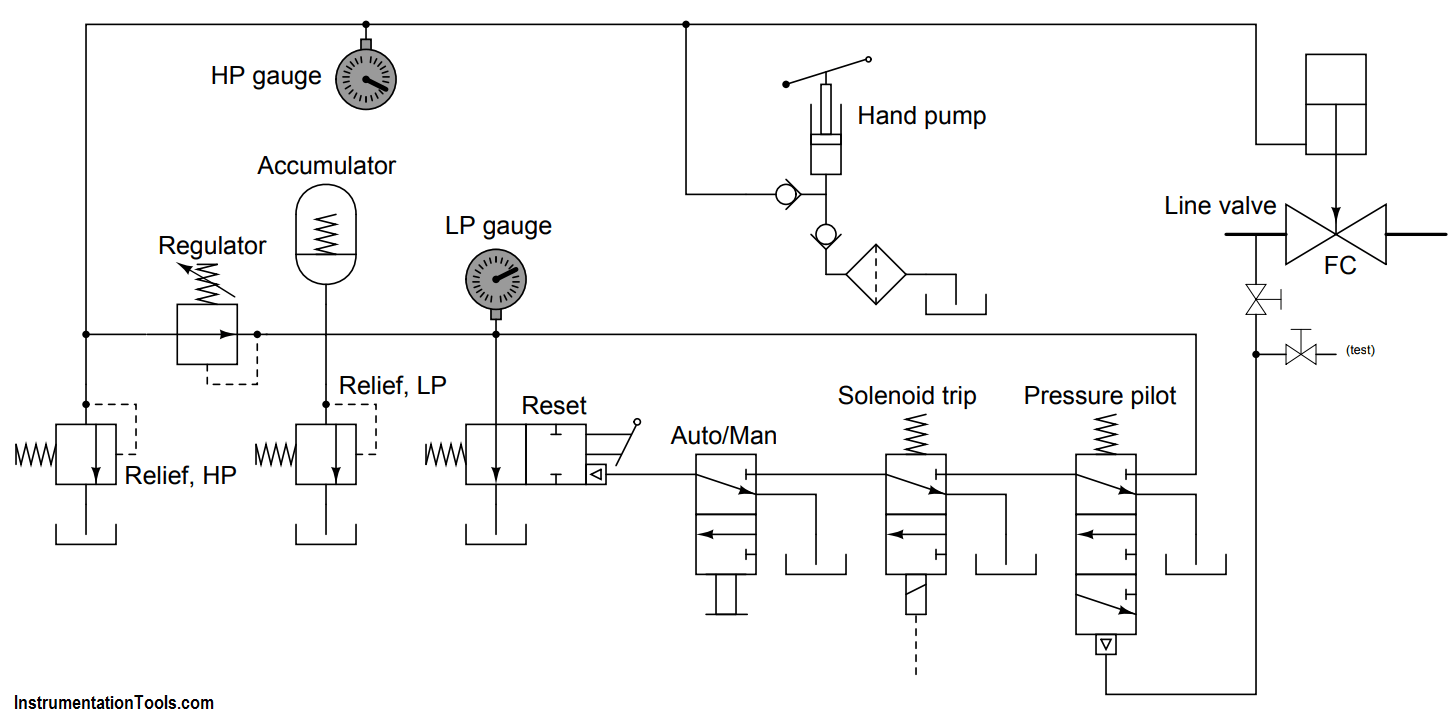
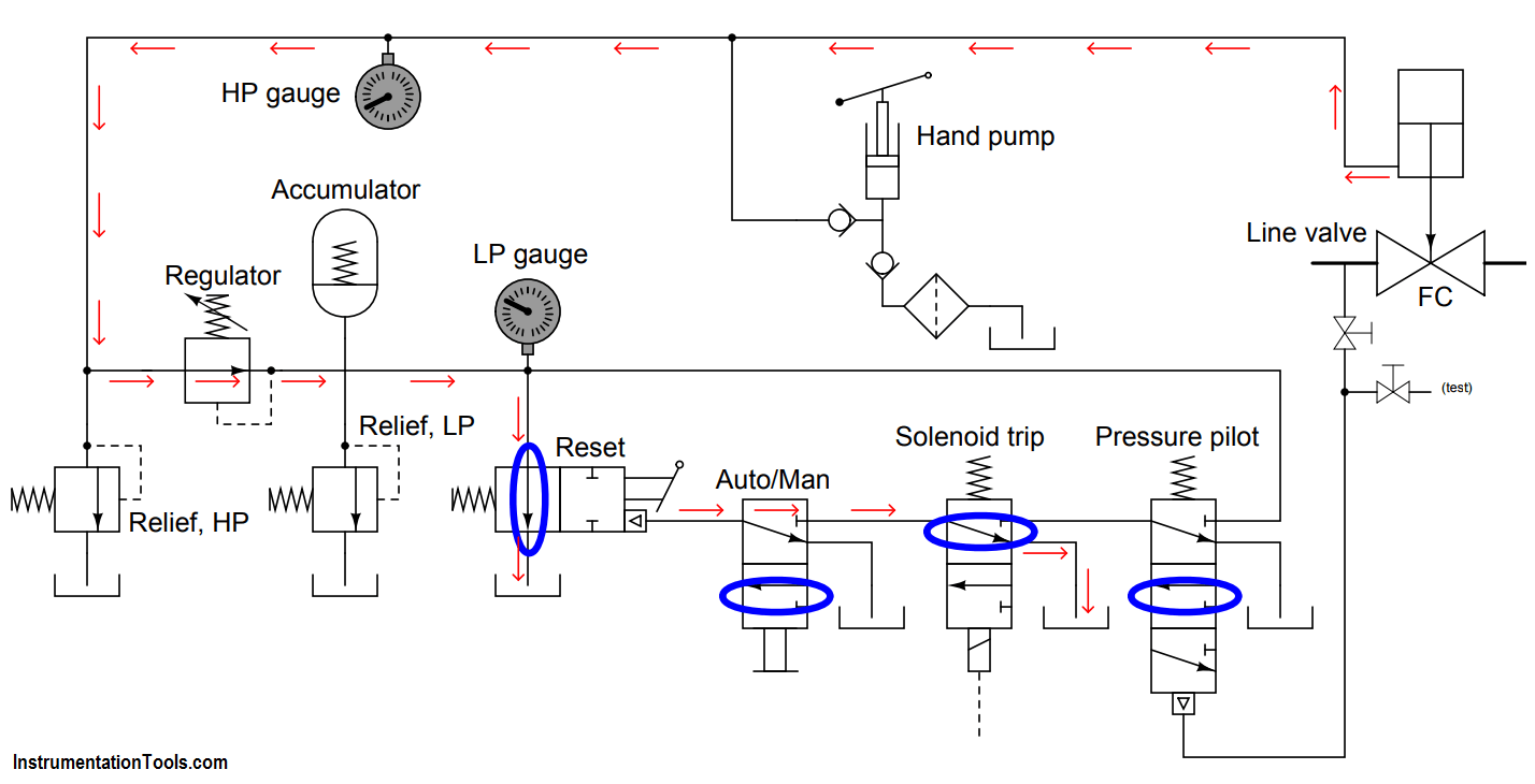
Identify all spool valve positions, and also trace the direction of oil flow, following a solenoid “trip” event.

Last updated: October 10, 2020 10:48 pm
Editorial Staff
Practical Questions
No Comments
Share
1 Min Read
SHARE

This fluid diagram shows the components and connections of a Bettis self-contained hydraulic module used to automatically shut off a “line valve” on a natural gas pipeline in the event of the pipeline pressure going outside of its limits (either falling below the low-pressure limit or rising above the high-pressure limit):

Identify all Spool Valve Positions

Identify all spool valve positions, and also trace the direction of oil flow, following a solenoid “trip” event.

Answer :

Natural gas pipeline valve

Read All SOV Questions & Answers
Solenoid Valves Questions & Answers – 1
Solenoid Valves Questions & Answers – 2
Solenoid Valves Questions & Answers – 3
Solenoid Valves Questions & Answers – 4
Solenoid Valves Questions & Answers – 5
Solenoid Valves Questions & Answers – 6
Solenoid Valves Questions & Answers – 7
Don't Miss Our Updates
Be the first to get exclusive content straight to your email.
We promise not to spam you. You can unsubscribe at any time.
Invalid email address
You've successfully subscribed !

Continue Reading

Draw Limit Switch Symbol ?
Air Pressure Regulator Questions
Differential Capacitance Pressure Sensor Circuit
Calculate the 0%, 50%, and 100% Calibration Points
Define Normal Status for each of the Process Switch
Purge Type Level Transmitter Questions
Share This Article
Facebook Whatsapp Whatsapp LinkedIn Copy Link
Share
Leave a Comment

Leave a Reply Cancel reply

Your email address will not be published. Required fields are marked *

Stay Connected

128.3kFollowersLike
69.1kFollowersFollow
210kSubscribersSubscribe
38kFollowersFollow

Categories

Explore More

Electronic Force Balance Pressure Transmitter
Pneumatic Force Balance Instrument
Problem on Weigh feeder
Measure the Temperature of the RTD
Calculate the Height of Glycerine
Calculate the Thermocouple Output millivolts
pH Transmitter Problem
Calculate 0%, 50%, and 100% Calibration Points for ΔP transmitter

Keep Learning

Draw the Symbols for Liquid Level Measuring Instruments

Draw the Symbols for Liquid Level Measuring Instruments

Calculate Amount of Weight Indicated by the Scale

Calculate Amount of Weight Indicated by the Scale

Stripper Overhead Temperature Control

Stripper Overhead Temperature Control System

Programmable Logic Controller (PLC) Questions and Answers

Programmable Logic Controller (PLC) Questions and Answers – 6

Calculate Incident Power in Radar Level Measurement

Calculate Incident Power in Radar Level Measurement

What Effect on Hydrostatic Level Transmitter if Liquid Density Changes?

What Effect on Hydrostatic Level Transmitter if Liquid Density Changes?

statuses of all lamps and relay coils in the circuit

Analyze the Relay Circuit and Find the Status ?

Electronic Pressure Sensor with Bourdon Tube and LVDT

Electronic Pressure Sensor with Bourdon Tube and LVDT

Learn More

Electromagnetic Fields Objective Questions

Electromagnetic Fields Objective Questions

fluid flow reversed through a Control Valve

What happens when Fluid Flow Reversed through Control Valve?

PLC Program for Food Processing

PLC Program for Food Processing Industry

Proximity Switch PNP Type Working Animation

Proximity switches Circuit Diagram Operation

RTD Calibration

RTD Calibration

Compressor IP Case Discharge Temperature Gradually Increases

Compressor Anti-Surge Control near-miss incident

Instrument Heat Trace

Electrical Heat Tracing

safety gas analyzer

Safety Gas Analyzers

Menu

  • About
  • Privacy Policy
  • Copyright

Quick Links

  • Learn PLC
  • Helping Hand
  • Part Time Job

YouTube Subscribe

Follow US
All rights reserved. Reproduction in whole or in part without written permission is prohibited.
Welcome Back!

Sign in to your account

Username or Email Address
Password

Lost your password?