Inst ToolsInst ToolsInst Tools
  • Courses
  • Automation
    • PLC
    • Control System
    • Safety System
    • Communication
    • Fire & Gas System
  • Instrumentation
    • Design
    • Pressure
    • Temperature
    • Flow
    • Level
    • Vibration
    • Analyzer
    • Control Valve
    • Switch
    • Calibration
    • Erection & Commissioning
  • Interview
    • Instrumentation
    • Electrical
    • Electronics
    • Practical
  • Q&A
    • Instrumentation
    • Control System
    • Electrical
    • Electronics
    • Analog Electronics
    • Digital Electronics
    • Power Electronics
    • Microprocessor
  • Request
Search
  • Books
  • Software
  • Projects
  • Process
  • Tools
  • Basics
  • Formula
  • Power Plant
  • Root Cause Analysis
  • Electrical Basics
  • Animation
  • Standards
  • 4-20 mA Course
  • Siemens PLC Course
Reading: Hydraulic System
Share
Notification Show More
Font ResizerAa
Inst ToolsInst Tools
Font ResizerAa
  • Courses
  • Design
  • PLC
  • Interview
  • Control System
Search
  • Courses
  • Automation
    • PLC
    • Control System
    • Safety System
    • Communication
    • Fire & Gas System
  • Instrumentation
    • Design
    • Pressure
    • Temperature
    • Flow
    • Level
    • Vibration
    • Analyzer
    • Control Valve
    • Switch
    • Calibration
    • Erection & Commissioning
  • Interview
    • Instrumentation
    • Electrical
    • Electronics
    • Practical
  • Q&A
    • Instrumentation
    • Control System
    • Electrical
    • Electronics
    • Analog Electronics
    • Digital Electronics
    • Power Electronics
    • Microprocessor
  • Request
Follow US
All rights reserved. Reproduction in whole or in part without written permission is prohibited.
Inst Tools > Blog > Process > Hydraulic System

Hydraulic System

Last updated: May 19, 2018 8:07 pm
Editorial Staff
Process
1 Comment
Share
6 Min Read
SHARE

Although any liquid can be used in a hydraulic system, some liquids have advantages over others. Oil is a liquid often preferred as the working fluid. Oil helps to lubricate the various sliding parts, prevents rust, and is readily available. For practical purposes, oil does not change its volume in the hydraulic system when the pressure is changed.

Pressure and Force

The foundation of modern hydraulic powered systems was established when a scientist named Blaise Pascal discovered that pressure in a fluid acts equally in all directions. This concept is known as Pascal’s Law. The application of Pascal’s Law requires the understanding of the relationship between force and pressure.

Force may be defined as a push or pull exerted against the total area of a surface. It is expressed in pounds. Pressure is the amount of force on a unit area of the surface. That is, pressure is the force acting upon one square inch of a surface. The relationship between pressure and force is expressed mathematically.

F = P x A

where:

F = force in lbf
P = pressure in lbf/in.2, (psi)
A = area in in.2

 Example 1:

In a hydraulic system, the oil pressure at the inlet to the cylinder is 1500 psi, and the area of the piston over which the oil pressure acts is two square inches. Calculate the force exerted on the piston.

Solution:

Since F = P x A, the force of the oil on the piston is calculated as follows.

F = 1500 lbf/in.2 x 2 in.2

F = 3000 lbf

Example 2:

A hydraulic valve requires a force of 1848 lbf to be opened. The piston area is 3 square inches. How much pressure does the hydraulic fluid have to exert for the valve to move?

Solution:

Since F = P x A, then P = F/A

P = 1848 lbf / 3 in.2

P = 616 lbf/in.2

Hydraulic Operation

The operation of a typical hydraulic system is illustrated in Figure 8. Oil from a tank or reservoir flows through a pipe into a pump. Often a filter is provided on the pump suction to remove impurities from the oil. The pump, usually a gear-type, positive displacement pump, can be driven by an electric motor, air motor, gas or steam turbine, or an internal combustion engine. The pump increases the pressure of the oil. The actual pressure developed depends upon the design of the system.

Most hydraulic systems have some method of preventing over-pressure. As seen in Figure 8, one method of pressure control involves returning hydraulic oil to the oil reservoir. The pressure control box shown on Figure 8 is usually a relief valve that provides a means of returning oil to the reservoir upon over-pressurization.

Hydraulic System

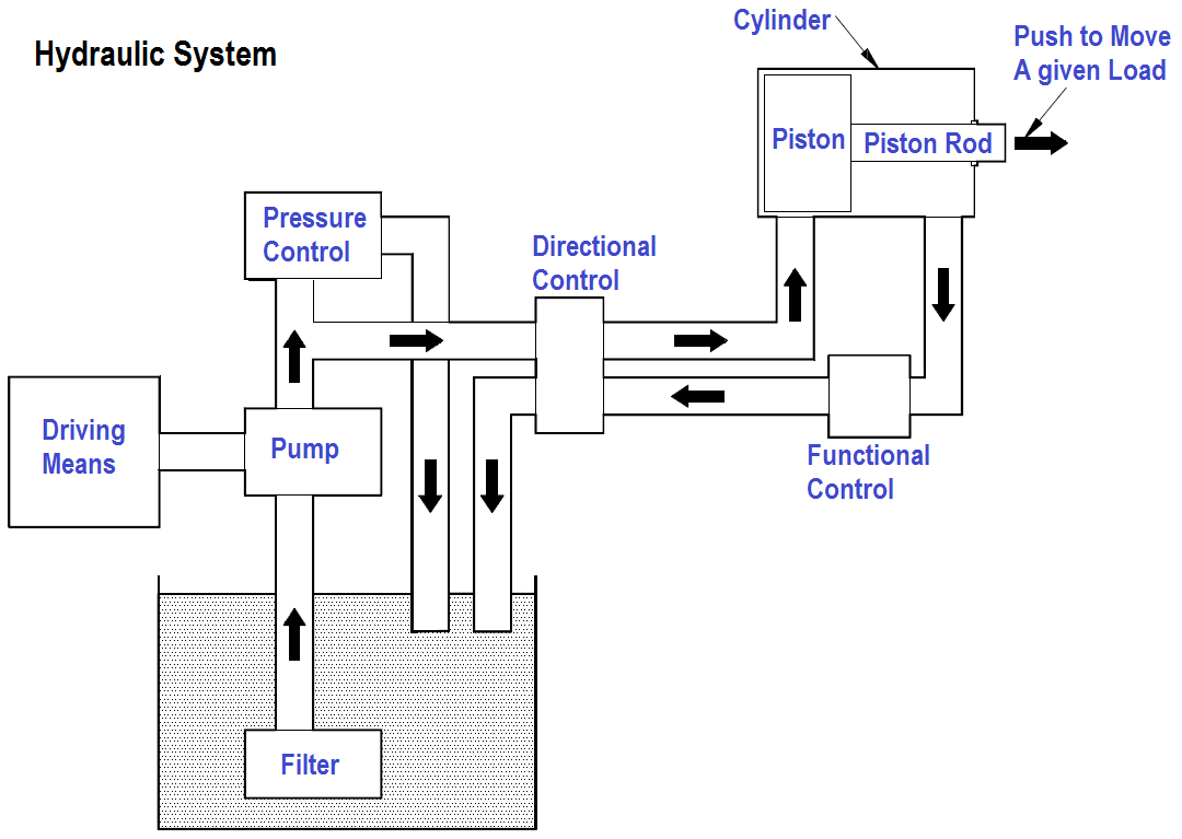
Figure 8 Basic Hydraulic System

The high pressure oil flows through a control valve (directional control). The control valve changes the direction of oil flow, depending upon the desired direction of the load. In Figure 8 the load can be moved to the left or to the right by changing the side of the piston to which the oil pressure is applied. The oil that enters the cylinder applies pressure over the area of the piston, developing a force on the piston rod. The force on the piston rod enables the movement of a load or device. The oil from the other side of the piston returns to a reservoir or tank.

Hazards

The hazards and precautions listed in the previous chapter on air compressors are applicable to hydraulic systems as well, because most of the hazards are associated with high pressure conditions. Any use of a pressurized medium can be dangerous. Hydraulic systems carry all the hazards of pressurized systems and special hazards that are related directly to the composition of the fluid used.

When using oil as a fluid in a high pressure hydraulic system, the possibility of fire or an explosion exists. A severe fire hazard is generated when a break in the high pressure piping occurs and the oil is vaporized into the atmosphere. Extra precautions against fire should be practiced in these areas.

If oil is pressurized by compressed air, an explosive hazard exists if the high pressure air comes into contact with the oil, because it may create a diesel effect and subsequent explosion. A carefully followed preventive maintenance plan is the best precaution against explosion.

Don't Miss Our Updates
Be the first to get exclusive content straight to your email.
We promise not to spam you. You can unsubscribe at any time.
Invalid email address
You've successfully subscribed !

Continue Reading

Filters in Compressors
Working of Air Compressor – Types – Control Techniques
Inhouse Moisture separator for Pneumatic Systems
Impulse Steam Trap
CO2 Stripper Collapsed Internals Revamp
Demineralizers
Share This Article
Facebook Whatsapp Whatsapp LinkedIn Copy Link
Share
1 Comment
  • RAYMOND MUTWIRA says:
    June 12, 2020 at 3:41 pm

    Thank you for very informative website

    Reply

Leave a Reply Cancel reply

Your email address will not be published. Required fields are marked *

Stay Connected

128.3kFollowersLike
69.1kFollowersFollow
210kSubscribersSubscribe
38kFollowersFollow

Categories

Explore More

Components of Water Treatment Plant
Discharge Head 3‑monthly leaks of Steam Turbine Driven Centrifugal Compressors
What is a Y Strainer ?
Pressure Reducing and DeSuperheating Station (PRDS)
Bellows Steam Trap
Cooling Tower
Strainers
Pressurizer

Keep Learning

Malfunctioning Inlet Check Valves

Malfunctioning Inlet Check Valves caused chaos at Compressor stop/trip

CO2 Absorber Graphics in DCS

CO2 Absorber Corroded Wall Thickness & Weld Building

Electro deionization in a Water Treatment Plant

What is EDI in a Water Treatment Plant? – Electro deionization

Precoat Filters

Precoat Filters

desuperheater

Concept of Desuperheater

Fuel Boiler

Boilers

Multi-Cartridge Filter

Cartridge Filters

Instrument Air (IA) System

Process Design of Instrument Air System

Learn More

3-way directional control valves

Directional Control Valves Working Principle

full-wave-bridge-rectifier-with-voltage-regulator

Basics of Voltage Regulators

Ladder Logic Example of Two Motors

Ladder Logic Example of Two Motors Interlinked with another Motor

Safety Relief Valve Questions & Answers

Safety Relief Valve Questions & Answers

transistor-base-bias

Transistor Base Bias

YouTube Channels About Tech and Engineering

Awesome YouTube Channels About Tech and Engineering

Power Electronics Objective Questions

Voltage Control in Inverters Objective Questions

Capacitance Type Level Transmitter Working Principle

Capacitance Level Transmitter Animation

Menu

  • About
  • Privacy Policy
  • Copyright

Quick Links

  • Learn PLC
  • Helping Hand
  • Part Time Job

YouTube Subscribe

Follow US
All rights reserved. Reproduction in whole or in part without written permission is prohibited.
Welcome Back!

Sign in to your account

Username or Email Address
Password

Lost your password?