If we searched about the purpose of Engineering, we will find that “Engineering is the application of science and mathematics to solve problems”.
However, nowadays this purpose has changed a little, in addition to solving the problems; you have to consider the cost of your solution.
Reducing costs and saving some money for your organization are the most important things that you can present to your company or factory.
Therefore, today we are going to learn how to save some money by the proper calculation of the cable sizing for your plant machines and equipment.
How to Size a Cable for Industrial AC Motors?
In this article, we will discuss how to do cable sizing for an industrial AC motor.
For calculating the size of any cable, you have to get through some steps.
- First Step is to determine the specification of your electric load:
Voltage (V): Specify the supply voltage and select the phase arrangement: 1 Phase AC or 3-phase AC. Load (kW, kVA, A, hp.): Specify the load in kW, kVA, A, or hp. In addition, you have to specify cos {Φ} (load power factor) when the load is specified in kW or hp.
Distance (m, ft.): The estimated cable or wire length in meters of feet.
Cable type: The number of cores in the cable.
Notice, “You can ignore the neutral and earth conductor in three-phase cables”.
Insulation type: The type of insulation. Typically Thermoplastic (PVC) or Thermoset (XLPE). The important part is to select the correct temperature rating.
Cable installation: How the cable is installed “Consider the worst-case section of the cable installation”.
- Second Step is to prepare the required tables.
The vendor of the electric cables has to provide the required tables of his products “Cables”
Therefore, by going to the vendor website you have to get:
- Cross-section area (CSA) Vs. Rated current table.
- Cross-section area (CSA) Vs. Voltage drop table.
- Third Step Calculating the voltage drop.
Using the load specification and vendor tables, you can calculate the estimated voltage drop across the cable.
Total Voltage Drop = Vd (V/Amp/Meter) * Max. Current (Amp) * Cable length (Meter)
- Forth Step Comparing the allowable voltage drop with the actual voltage drop
According to (IEEE Rule B-23):
“At any point between a power supply terminal and installation, voltage drop should not increase above 2.5% of provided (supply) voltage.”
If the calculated voltage drop < allowable voltage drop then the designed CSA is accepted.
If the calculated voltage drop > allowable voltage drop then you have to choose a higher CSA.
Motor Cable Sizing Example Calculation
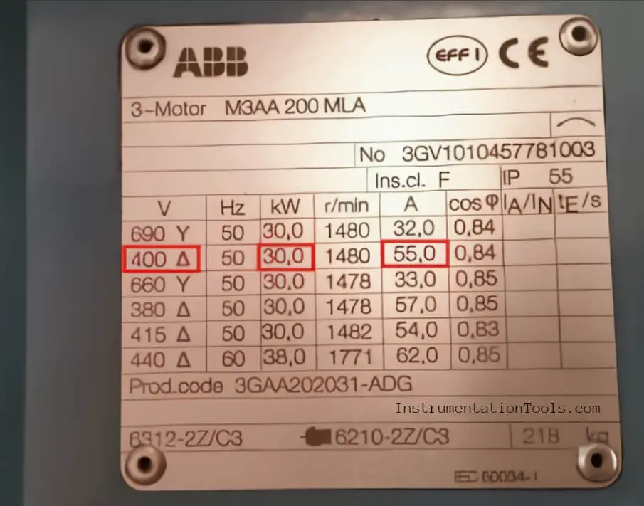
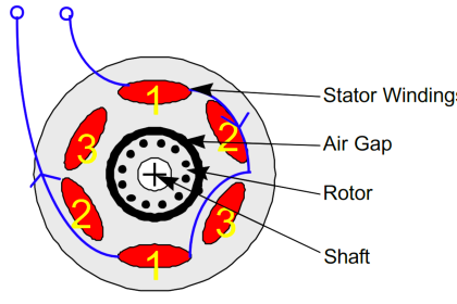
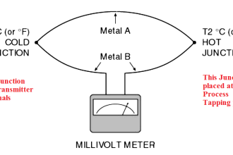
Here we have in Fig. (1) an example of a Three-phase induction motor that you are supposed to calculate the size of its cable.
By starting with our first step “Determining Load Specification”:
- Supply voltage = 400 V
- Power = 30 KW
- Rated Current = 55 A
- Max. Expected current = 1.5 * Rated current = 82.5 A
Notice that you have to keep in mind the over-loaded current and to have a kind of safe margin so you should make your calculation on 1.5 of the rated current.
- Cable distance = 110 M
- Cable type: Multicore Cables, with Stranded Copper Conductors, PVC Insulated and PVC Sheathed.
- Cable Installation: Laid in free air.
Now by going through the next step “Cable Specification Table”:
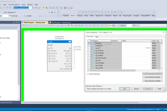
- According to ELSEWEDY ELECTRIC Power Cable catalog: Shown in Fig. (2)
As the current rate for the selected size is bigger than the Max. Expected current.
The first estimation would be (CP1-T104-U11) with a CSA of 16 mm2 (Current rating = 83 A)
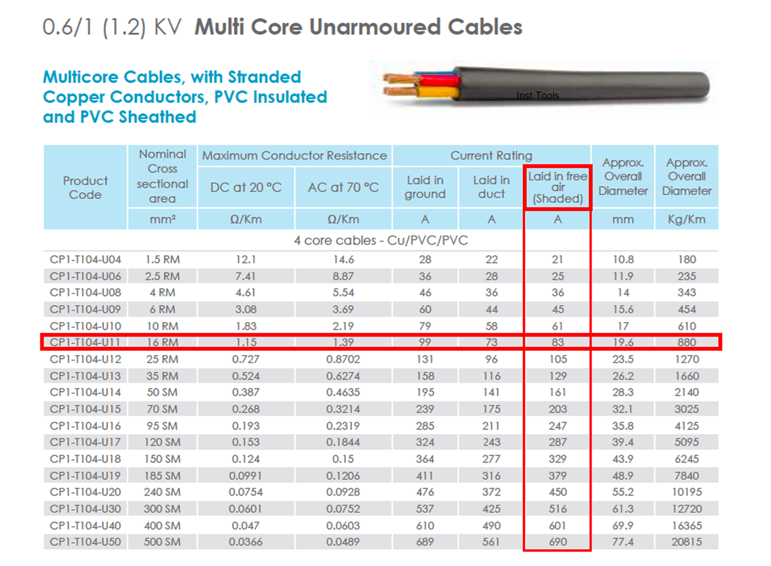
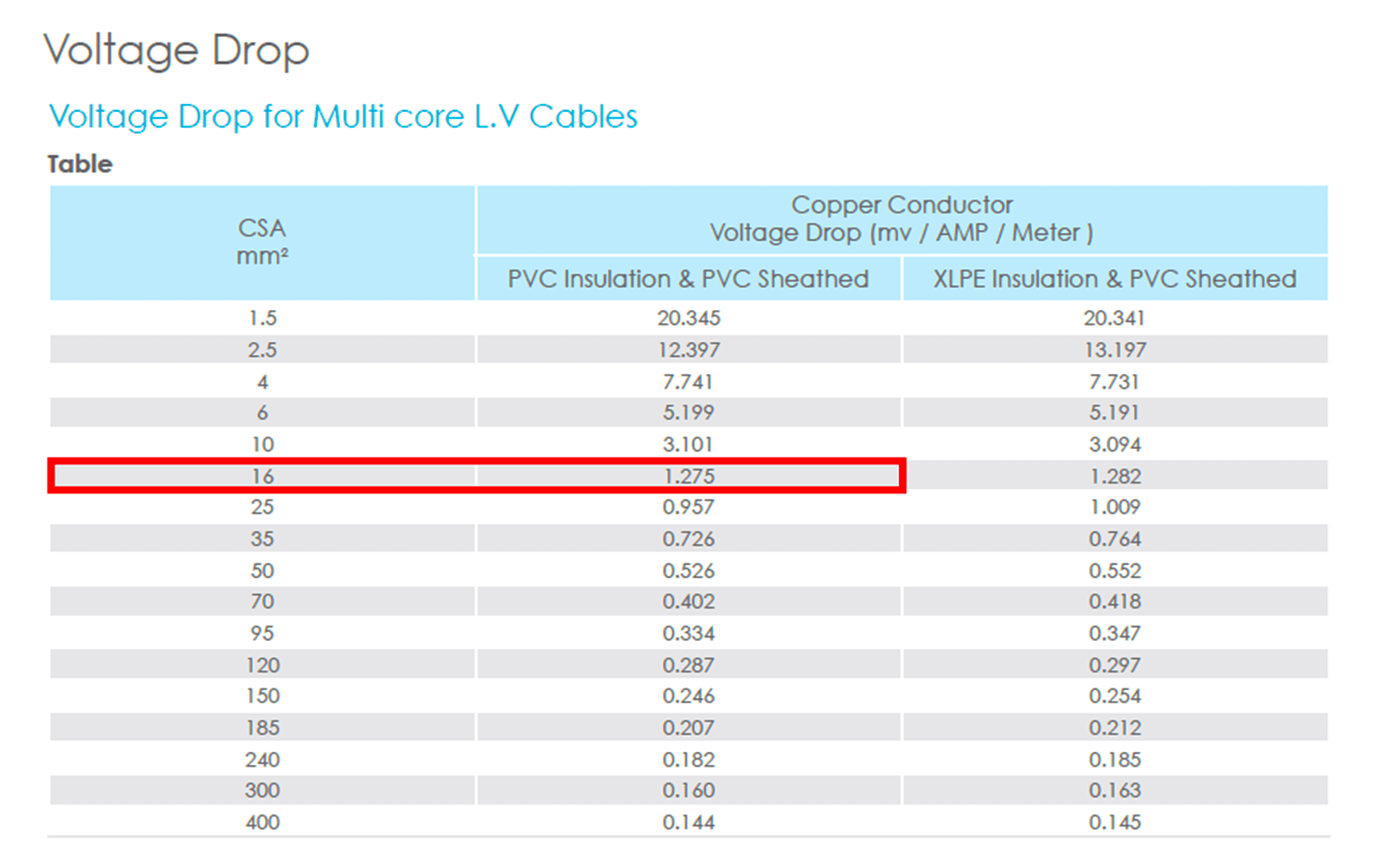
- According to ELSEWEDY ELECTRIC Power Cable catalog: Shown in Fig. (3)
The equivalent voltage drop for this CSA (16 mm2) is 1.275 (mv / AMP / Meter)
Now for the third step “Calculating the Voltage Drop”
As we said before:
Total Voltage Drop = Vd (V/Amp/Meter) * Max. Current (Amp) * Cable length (Meter)
Allowable Voltage Drop = 2.5% Supply Voltage
Then:
VD = 1.275 * 0.001 * 82.5 * 110 = 11.57 V
AVD = 400 * 0.025 = 10 V
By “comparing the allowable voltage drop with the actual voltage drop”, we can find that:
Total Voltage Drop > Allowable Voltage Drop
Then the designed CSA is not accepted so we have to select the next bigger CSA from our tables and recalculate the voltage drop again to see if the new estimated CSA can fit our application or not.
—————————————————————————————————
By returning to Fig. (2) & (3)
The new CSA would be 25 mm2 (Current rating = 105 A), and the equivalent voltage drop for this CSA (25 mm2) is 0.957 (mv / AMP / Meter)
Then:
VD = 0.957 * 0.001 * 82.5 * 110 = 8.68 V
AVD = 400 * 0.025 = 10 V
By comparing the allowable voltage drop with the actual voltage drop, we can find that:
Total Voltage Drop < Allowable Voltage Drop
Finally, the designed CSA is accepted as the voltage drop is accepted then the selected cable is (CSA = 25 mm2)


Why you have not considered power factor??
Also what is 0.001 used in voltage drop calculations?
Hello, I hope you are doing great…
Power factor is already considered as you can see in Fig. (1) rated current at PF (0.84) which is lower than the value of the PF in my plant. it depends on your factory.
(0.001) to convert from mV to V
If we have done the calculation related to the voltage drop, and because we installing a pump in 300-400 meter distance, causing the CSA of the cable is bigger than the terminal block of our electromotor, what should we do?
Hello Dimas,
The expected answer would be to change the terminal block ((BUT)) if you can not you can duplicate your cable.
Assume you need a CSA (70mmSq) for 400m you can connect your motor with two cables with CSA (35mmSq) then you can use your terminal block but you have to duplicate them also.
Summary.. instead of using a single 70mmSq cable you can use two cables with CSA 35mmSq.
How can we calculate area of cable without considering cable size chart?
Voltage drop calculated(R x Amps x Length) is for single phase(i.e for each line). Hence, 2.5% of Rated voltage should be 2.5% of Ph.N voltage -> 240 x 2.5/100 = 6V (should not be 415 x 2.5/100 ). And also, you have not mentioned about voltage drop limits applicable w.r.t starting current of motor in case of DOL Starter.