Inst ToolsInst ToolsInst Tools
  • Courses
  • Automation
    • PLC
    • Control System
    • Safety System
    • Communication
    • Fire & Gas System
  • Instrumentation
    • Design
    • Pressure
    • Temperature
    • Flow
    • Level
    • Vibration
    • Analyzer
    • Control Valve
    • Switch
    • Calibration
    • Erection & Commissioning
  • Interview
    • Instrumentation
    • Electrical
    • Electronics
    • Practical
  • Q&A
    • Instrumentation
    • Control System
    • Electrical
    • Electronics
    • Analog Electronics
    • Digital Electronics
    • Power Electronics
    • Microprocessor
  • Request
Search
  • Books
  • Software
  • Projects
  • Process
  • Tools
  • Basics
  • Formula
  • Power Plant
  • Root Cause Analysis
  • Electrical Basics
  • Animation
  • Standards
  • 4-20 mA Course
  • Siemens PLC Course
Reading: How to Select a Directional Valves
Share
Notification Show More
Font ResizerAa
Inst ToolsInst Tools
Font ResizerAa
  • Courses
  • Design
  • PLC
  • Interview
  • Control System
Search
  • Courses
  • Automation
    • PLC
    • Control System
    • Safety System
    • Communication
    • Fire & Gas System
  • Instrumentation
    • Design
    • Pressure
    • Temperature
    • Flow
    • Level
    • Vibration
    • Analyzer
    • Control Valve
    • Switch
    • Calibration
    • Erection & Commissioning
  • Interview
    • Instrumentation
    • Electrical
    • Electronics
    • Practical
  • Q&A
    • Instrumentation
    • Control System
    • Electrical
    • Electronics
    • Analog Electronics
    • Digital Electronics
    • Power Electronics
    • Microprocessor
  • Request
Follow US
All rights reserved. Reproduction in whole or in part without written permission is prohibited.
Inst Tools > Blog > Instrumentation Design > How to Select a Directional Valves

How to Select a Directional Valves

Last updated: March 18, 2017 6:15 am
Editorial Staff
Instrumentation Design
No Comments
Share
4 Min Read
SHARE

Top 5 Things You Need to Know When Selecting Directional Valves

Selecting the right valve to control system pressure, direction of flow and rate of flow is crucial when designing fluid power circuitry. Below are the top 5 things that must be considered when specifying directional valves for any pneumatic application.

Selecting Directional Valves

1. Function
Directional valves are used to control fluid direction within a pneumatic circuit. The action required by your application will determine the type of valve needed.

  • 2-way valves are only used to allow or stop fluid flow, providing a simple on and off function in a pneumatic circuit.
  • 3-way valves feature three passages within a valve body which are used to pressurize and exhaust a port. These valves are primarily used to operate single-acting actuators such as spring-return cylinders.
  • 4-way valves are one of the most commonly used pneumatic components for directional control. With four distinct flow paths, these valves make it easy to reverse the motion of a cylinder or motor.

2. Actuator Style
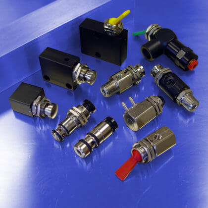
Depending on your application requirements, a variety of methods are available to actuate a directional valve.

  • Manual controls include push buttons and detented or momentary toggles.
  • Ball and pin (plunger) style operators are ideal for mechanical actuation.
  • Solenoid operators are used as an interface to convert electrical signals into pneumatic functions.
  • Air pilot operators are ideal for using air pressure to actuate a directional valve at a remote location.

3. Flow Rate
How much flow do you need at the output port of the valve? It is important to know the required flow rate of your application in order to correctly size a directional control valve. If the valve is too big for the application, you will be wasting air & money. If it’s too small, the actuator will not function properly.

Flow rate is typically measured in standard cubic feet per minute (scfm) passing through a valve at a specified operating pressure (psi). Another common measurement is standard cubic feet per hour (scfh).

4. Operating Pressure
The pressure required to operate a directional valve is known as the operating pressure (psi). Since operating pressure greatly affects flow rate, it is important to review the performance data presented by the manufacturer to ensure that a valve will perform as required in your application. For example, at 50 psi a valve can have a flow rate of 9 scfm whereas at 125 psi, the same valve has a flow rate of 20 scfm. Most pneumatic valves are rated for use with vacuum (26” Hg) to 150 psi.

5. Media Compatibility
When using any media other than air, it is important to review the materials of construction to ensure that the internal components and seals are compatible with the fluid passing through the valve.

Also Read: How to Select a Solenoid Valve

Don't Miss Our Updates
Be the first to get exclusive content straight to your email.
We promise not to spam you. You can unsubscribe at any time.
Invalid email address
You've successfully subscribed !

Continue Reading

Package System Architecture – Control & Instrumentation
Compliance Table Application (for Procurement Service Cycle)
Cut-outs between Platforms or Grating for Field Instruments
How to Calculate Transmitter Performance and Calibration Frequency?
How to Select a pH or ORP Meter
How to Minimize Water Vapor in Instrument Air Lines?
Share This Article
Facebook Whatsapp Whatsapp LinkedIn Copy Link
Share
Leave a Comment

Leave a Reply Cancel reply

Your email address will not be published. Required fields are marked *

Stay Connected

128.3kFollowersLike
69.1kFollowersFollow
210kSubscribersSubscribe
38kFollowersFollow

Categories

Explore More

Competency Factors of Instrument & Control Engineer (Design Engineering)
Important Factors for Thermocouple Selection
Instrument Process Datasheet (IPDS)
Instrument Air Compressor Control Philosophy
Turbine-Compressor System Architecture
How to choose between PLC and DCS Systems ?
Control Valve Selection Tips
History of 3-15 psi, 10-50 mA, and 4-20 mA signals

Keep Learning

Earth Meter Working Principle

How Earth Resistance is Measured

Axial Diaphragm Seal Connection

Difference between Axial and Radial Diaphragm Seal Connection?

Load Cell Design

Load Cell Design

Temperature Sensor Failure

Temperature Sensor Failure

Field Instruments

Is Vacuum affects Field Instruments in Industries?

Orifice Beta

Why is Orifice Beta in between 0.3 to 0.7?

Instrument Air (IA) System

Process Design of Instrument Air System

Failsafe interlock Design

Failsafe Wiring Practices

Learn More

Calculate Total Hydrostatic Pressure at Bottom of Vessel

Calculate Total Hydrostatic Pressure at Bottom of Vessel

Control Systems Stability and Algebraic Criteria

Concept of Stability in Control Systems

Power Electronics Objective Questions

Single-Phase Half Wave AC-DC Converter MCQ

What is Averaging Pitot Tube

What is an Averaging Pitot Tube? – Principle, Advantages

Power System Interview Question and Answers

Power System Interview Question and Answers

Variable Area Flow Meters

All About Variable Area Flow Meters

Introduction to GOC controllers

Mitsubishi Electric GOC Controllers

Closed-Tank-DP-Type-Level-Measurement-with-wet-leg-and-transmitter-installed-below-tapping-point

Level Measurement with Wet leg and Installed Below Tapping Point

Menu

  • About
  • Privacy Policy
  • Copyright

Quick Links

  • Learn PLC
  • Helping Hand
  • Part Time Job

YouTube Subscribe

Follow US
All rights reserved. Reproduction in whole or in part without written permission is prohibited.
Welcome Back!

Sign in to your account

Username or Email Address
Password

Lost your password?