Inst ToolsInst ToolsInst Tools
  • Ask
  • Courses
  • Videos
  • Q & A
    • Interview
      • Instrumentation
      • Electronics
      • Electrical
      • Practical Questions
    • MCQ
      • Instrumentation MCQ
      • Electrical MCQ
      • Electronics MCQ
      • Control Systems MCQ
      • Analog Electronics MCQ
      • Digital Electronics MCQ
      • Power Electronics MCQ
      • Microprocessor MCQ
      • Multiple Choice Questions
  • EE
    • Electronics
      • Electronics Q & A
      • Electronic Basics
      • Electronic Devices & Circuits
      • Electronics Animation
      • Digital Electronics
    • Electrical
      • Electrical Basics
      • Electrical Q & A
      • Power Electronics
      • Electrical Machines
      • Electrical Animation
      • Power Systems
      • Switchgear & Protection
      • Transmission & Distribution
  • Measure
    • Control Valves
    • Calibration
    • Temperature
    • Pressure
    • Flow
    • Level
    • Analyzers
    • Switches
    • Vibration
    • Solenoid Valve
  • Control
    • PLC Tutorials
    • Control Systems
    • Safety Instrumented System (SIS)
    • Communication
    • Fire & Gas System
  • More
    • Design
    • Tools
    • Animation
    • Basics
    • Formulas
    • Standards
    • TextBooks
    • Common
    • Software
    • Excel Tools
    • Erection & Commissioning
    • Process Fundamentals
    • Videos
    • Books
Search
All rights reserved. Reproduction in whole or in part without written permission is prohibited.
Reading: How to measure frequency using Multimeter
Share
Notification Show More
Font ResizerAa
Inst ToolsInst Tools
Font ResizerAa
  • Courses
  • PLC Tutorials
  • Control Systems
Search
  • Ask
  • Courses
  • Videos
  • Q & A
    • Interview
    • MCQ
  • EE
    • Electronics
    • Electrical
  • Measure
    • Control Valves
    • Calibration
    • Temperature
    • Pressure
    • Flow
    • Level
    • Analyzers
    • Switches
    • Vibration
    • Solenoid Valve
  • Control
    • PLC Tutorials
    • Control Systems
    • Safety Instrumented System (SIS)
    • Communication
    • Fire & Gas System
  • More
    • Design
    • Tools
    • Animation
    • Basics
    • Formulas
    • Standards
    • TextBooks
    • Common
    • Software
    • Excel Tools
    • Erection & Commissioning
    • Process Fundamentals
    • Videos
    • Books
Follow US
All rights reserved. Reproduction in whole or in part without written permission is prohibited.
Inst Tools > Blog > Electronic Basics > How to measure frequency using Multimeter

How to measure frequency using Multimeter

Last updated: April 27, 2017 4:21 am
Editorial Staff
Electronic Basics
1 Comment
Share
4 Min Read
SHARE

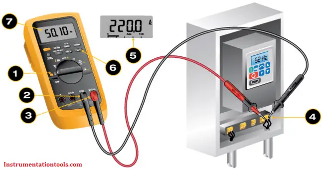
If your digital multimeter offers a frequency setting (Hz is the symbol) on the dial:

  1. Turn the dial to Hz. It usually shares a spot on the dial with at least one other function. Some meters enter the frequency through a secondary function accessed by pushing a button and setting the rotary switch to ac or dc.
  2. First insert the black test lead into the COM jack.
  3. Then insert the red lead into the V Ω jack. When finished, remove the leads in reverse order: red first, then black.
  4. Connect the black test lead first, the red test lead second. When finished, remove the leads in reverse order: red first, then black.
  5. Read the measurement in the display. The abbreviation Hz should appear to the right of the reading.

If your digital multimeter offers a frequency (Hz) button:

Measure Frequency using Multimeter

  1. Turn the dial to ac voltage ( ). If voltage in the circuit is unknown, set the range to highest voltage setting.
    Note: Most digital multimeters power up in Autorange mode, automatically selecting the measurement range based on the voltage present.
  2. First insert the black test lead into the COM jack.
  3. Then insert the red lead into the V Ω jack.
  4. Connect the test leads to the circuit. The position of the test leads is arbitrary. When finished, remove the leads in reverse order: red first, then black.
  5. Read the voltage measurement in the display.
  6. With the multimeter still connected to the circuit, press the Hz button.
  7. Read the frequency measurement in the display. The Hz symbol should appear in the display to the right of the measurement.

Frequency measurement overview

Circuits and equipment may be designed to operate at a fixed or variable frequency. They may perform abnormally if operated at a different frequency than specified.

Example: An ac motor designed to operate at 60 Hz operates slower if the frequency is less than 60 Hz, or faster if frequency exceeds 60 Hz. For ac motors, any change in frequency causes a proportional change in motor speed. A five percent reduction in frequency yields a five percent reduction in motor speed.

Some digital multimeters include optional modes related to frequency measurement:

  • Frequency Counter mode: It measures the frequency of ac signals. It can be used to measure frequency when troubleshooting electrical and electronic equipment.
  • MIN MAX Recording mode: Permits frequency measurements to be recorded over a specific time period. It provides the same function with voltage, current and resistance.
  • Autorange mode: Automatically selects the frequency measurement range. If the frequency of the measured voltage is outside of the frequency measurement range, a DMM cannot display an accurate measurement. Refer to the user’s manual for specific frequency measurement ranges

In some circuits, there may be enough distortion on the line to prevent an accurate frequency measurement. Example: ac variable frequency drives (VFDs) can produce frequency distortions.

When testing VFDs, use the low-pass filter setting in the advanced multimeters for accurate readings. For multimeters without the low pass filter  setting, turn the dial to dc voltage, then press the Hz button again to measure the frequency on the dc voltage setting. If the meter allows for a decoupled frequency measurement, you might also try changing the voltage range to compensate for the noise.

Source : Fluke

Also Read: How to Test a Diode

Don't Miss Our Updates
Be the first to get exclusive content straight to your email.
We promise not to spam you. You can unsubscribe at any time.
Invalid email address
You've successfully subscribed !
How to Measure capacitance using Multimeter
What is PCB Corrosion? Electronic Boards Corrosion Prevention
Difference Between LDR and Photodiode
How to Measure Duty Cycle using Multimeter
How are Silicon Chips Disposed?
Share This Article
Facebook Whatsapp Whatsapp LinkedIn Copy Link
Share
1 Comment
  • GEORGE PRITCHARD says:
    August 14, 2023 at 12:03 pm

    my multimeter doesn’t have HZ are there any other methods of measureing

    Reply

Leave a Reply Cancel reply

Your email address will not be published. Required fields are marked *

Stay Connected

128.3kFollowersLike
69.1kFollowersFollow
208kSubscribersSubscribe
38kFollowersFollow

Categories

Recent Comments

  • Guifty Shimica on Top Non-PLC Certification Courses for Automation Professionals
  • Guifty Shimica on Top Non-PLC Certification Courses for Automation Professionals
  • MIHARITSOA Aina Sitraka on Top Non-PLC Certification Courses for Automation Professionals
  • Vaishnavi on Free Instrumentation Course for Trainee Engineers

Related Articles

resistor-color-coding-example

IEC labelling for Resistors Color Code

Switched Mode Power Supply (SMPS)

How does SMPS Works? – Switched Mode Power Supply

Testing a defective transistor

Testing a Transistor with a Digital Multimeter

Open Diode in a Full-Wave Rectifier

Power Supply Circuit Fault Analysis

Electrical Wire Mesh

What is an Electrical Wire Mesh?

Types of Inductors

What is an Inductor? – Types of Inductors

Difference between Analog Signal and Digital Signal

What are Analog and Digital Signals? Differences, Examples

Power Supply Voltage Regulator Problem

Troubleshooting a Power Supply Circuit

More Articles

Top 100 PLC Projects List

Top 100 PLC Projects List

Centrifugal Machine Field

Batch Type Centrifugal Automation in Sugar Industries

Valve Actuator Passing

Lessons Learned from Actuator Passing Incidents

Level Sensors

Advantages & Disadvantages of Level Measurement Systems

PLC programming for clothes washing machine automation

LS Electric PLC Program Example: Clothes Washing System

Concept of DCS in Industrial Automation

Concept of DCS in Industrial Automation

Instrument Zero and Span Calibration

Instrument Zero and Span Calibration

Why 4-20 mA Current Signal is used instead of Voltage Signal

Why 4-20 mA Current Signal is used instead of Voltage Signal?

Follow US
All rights reserved. Reproduction in whole or in part without written permission is prohibited.
Welcome Back!

Sign in to your account

Username or Email Address
Password

Lost your password?