Coriolis mass flow meter is also capable of giving the density of the flowing fluid, it operates on the same principle as the spring and mass assembly as shown in the diagram below.
When the suspended mass is pulled down and released, it will move up and down, its motion both driven and limited by the spring, until the vibration is damped. The number of complete oscillations per unit of time is referred to as the frequency of oscillation.
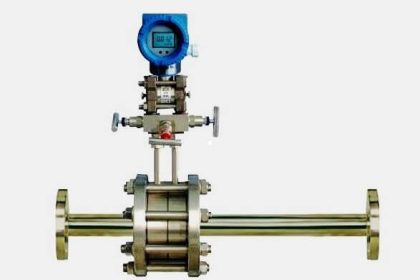
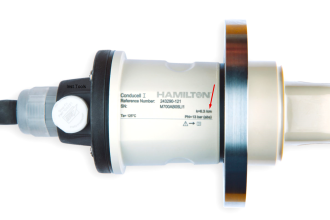
Coriolis Mass Flow Meter

As long as the mass of the object attached to the spring remains the same, whenever the object is pulled and released, the system settles to the same frequency until the movement is damped. This is referred to as the Natural frequency of the system.
If the amount of mass changes, the natural frequency of the system changes;
- If the mass is increased, the natural frequency decreases; the weight and spring make fewer oscillations per unit of time.
- If the mass is decreased, the natural frequency increases; the weight and spring make more oscillations per unit of time.
The frequency of oscillation is inversely proportional to the square root of the mass.
Formula
The exact relationship is expressed by the formula;

where;
f = the frequency
m = mass of the tube
K = constant representing the response of the spring
In the Coriolis mass-flow meter, the oscillating tubes correspond to the spring, and the mass of the tubes plus the mass of their contents corresponds to the mass of the spring assembly.
The drive coil that oscillates the flow tubes is energized periodically through a feedback circuit so that the tubes are always oscillating at their natural frequency.
Density is inversely proportional to the square of the frequency.
The equation is ;

where;
f = the frequency
m = mass of the tube
V = volume of the tube
K = constant representing the response of the spring
Since the volume and mass of the tubes and the spring constant do not change, the density of the fluid can be derived from the frequency of oscillation of the sensor which is mounted on the Coriolis flow tubes.
If you liked this article, then please subscribe to our YouTube Channel for Instrumentation, Electrical, PLC, and SCADA video tutorials.
You can also follow us on Facebook and Twitter to receive daily updates.
Read Next:
- Flow Measurement MCQ
- Thermal Dispersion Switch
- InLine Flow Switch Working
- What is an Orifice Meter?
- Flow meters Animation


Hello sir your website instrumentation tool is very good platform to learn for instrumentation engineers I am graduate from electronics and instrumentation branch and now working in control and instrumentation department in thermal power plant sir as you know that there is very much awareness regarding the instrumentation core field scope for the instrumentation branch student, your website is a very good platform to them to learn and to make feel that there are a lot of interesting thing to learn in instrumentation field, sir if I can help you in any manner To make website more useful than please give me chance to help or to assist you thank you very much
It is important to note that the early mass meters used the mains frequency to drive the tubes into vibration, typically 50 or 60Hz. It is only when they changed to resonant frequency that density was measurable.
The treatment here is a very good introduction but in reality there are a number of effects that must be compensated for.
Temperature: Firstly a correction between the calibration temperature and the operating temperature
Secondly the temperature effect on stiffness which depends also on materials of construction.
The pressure effect which also affects tube stiffness, ad high viscosity….. this tends to shift the resonant frequency to lower
values.
Velocity of sound effects.
With Hydrocarbons one may also have to take account of the correction factors in the Manual Of Petroleum Measurement Standards.
How density measured in mass flow meter?