By using this site, you agree to the Privacy Policy and Terms of Use.
Accept
Inst ToolsInst ToolsInst Tools
  • Ask
  • Courses
  • Videos
  • Q & A
    • Interview
      • Instrumentation
      • Electronics
      • Electrical
      • Practical Questions
    • MCQ
      • Instrumentation MCQ
      • Electrical MCQ
      • Electronics MCQ
      • Control Systems MCQ
      • Analog Electronics MCQ
      • Digital Electronics MCQ
      • Power Electronics MCQ
      • Microprocessor MCQ
      • Multiple Choice Questions
  • EE
    • Electronics
      • Electronics Q & A
      • Electronic Basics
      • Electronic Devices & Circuits
      • Electronics Animation
      • Digital Electronics
    • Electrical
      • Electrical Basics
      • Electrical Q & A
      • Power Electronics
      • Electrical Machines
      • Electrical Animation
      • Power Systems
      • Switchgear & Protection
      • Transmission & Distribution
  • Measure
    • Control Valves
    • Calibration
    • Temperature
    • Pressure
    • Flow
    • Level
    • Analyzers
    • Switches
    • Vibration
    • Solenoid Valve
  • Control
    • PLC Tutorials
    • Control Systems
    • Safety Instrumented System (SIS)
    • Communication
    • Fire & Gas System
  • More
    • Design
    • Tools
    • Animation
    • Basics
    • Formulas
    • Standards
    • TextBooks
    • Common
    • Software
    • Excel Tools
    • Erection & Commissioning
    • Process Fundamentals
    • Videos
    • Books
Search
All rights reserved. Reproduction in whole or in part without written permission is prohibited.
Reading: H1 FF Data Link layer
Share
Notification Show More
Font ResizerAa
Inst ToolsInst Tools
Font ResizerAa
  • Ask
  • Courses
  • Videos
  • Q & A
  • EE
  • Measure
  • Control
  • More
Search
  • Ask
  • Courses
  • Videos
  • Q & A
    • Interview
    • MCQ
  • EE
    • Electronics
    • Electrical
  • Measure
    • Control Valves
    • Calibration
    • Temperature
    • Pressure
    • Flow
    • Level
    • Analyzers
    • Switches
    • Vibration
    • Solenoid Valve
  • Control
    • PLC Tutorials
    • Control Systems
    • Safety Instrumented System (SIS)
    • Communication
    • Fire & Gas System
  • More
    • Design
    • Tools
    • Animation
    • Basics
    • Formulas
    • Standards
    • TextBooks
    • Common
    • Software
    • Excel Tools
    • Erection & Commissioning
    • Process Fundamentals
    • Videos
    • Books
Follow US
All rights reserved. Reproduction in whole or in part without written permission is prohibited.
Inst Tools > Blog > Communication > H1 FF Data Link layer

H1 FF Data Link layer

Last updated: March 29, 2018 7:51 am
Editorial Staff
Communication
No Comments
Share
4 Min Read
SHARE

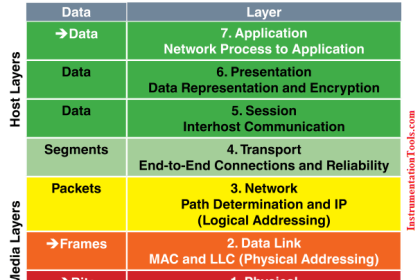
Like so many other industrial data networks, FOUNDATION Fieldbus is an “unswitched” or “broadcast” type of network. This means all data transmissions by all devices on a network are sensed by all the other devices. In other words, there are no private messages between two devices on a shared network: every device “hears” every transmission from every other device. This means devices must take turns communicating, with no simultaneous transmissions. Layer 2 of the OSI Reference Model is where we define the “data link” elements of a digital data network, describing how individual devices negotiate for the right to transmit on the network. Here is a list of some layer-2 properties of H1 FF networks:

  • Master/slave network behavior for cyclic communications (i.e. one device polls the others, and the others merely respond)
  • Delegated token network behavior for acyclic communications (i.e. devices serially granted time to broadcast at will)
  • Dedicated “scheduler” device for coordinating all segment communications
  • 8-bit address field (0 through 255 possible)
  • Maximum of 32 “live” devices on a segment

On an operating H1 segment, one device called the Link Active Scheduler (abbreviated LAS) functions as the “master” device for coordinating all network communications, analogous to a police officer directing traffic in a road intersection. The LAS device may be a regular field instrument (e.g. transmitter, valve positioner) or it may be the host system (i.e. the H1 segment interface card of a DCS). The FF standard allows for one operating LAS device, with multiple back-up LAS devices waiting to take over if the primary LAS happens to fail for any reason.

One of the tasks of the LAS is to “compel” the various field instruments to transmit their process control data (process variables, PID control output values, and other variables essential for loop monitoring and control), while the devices immediately respond in answer to the LAS’s “compel data” command. These critical communications occur on a regular schedule, and therefore are referred to as scheduled or cyclic communications. Cyclic communication operates in a “master-slave” fashion, with the LAS acting as the master (commanding slave devices to broadcast specific data), and all other devices responding only when called upon by the LAS. This form of communication is analogous to a traffic policeman specifically directing one vehicle at a time to drive through an intersection in a prescribed manner.

Periods of time in between these critical transmissions on an H1 network are used for device’s internal processing (e.g. PID algorithm execution, diagnostic checking) and also for less-critical data transmission. It is during these unscheduled or acyclic times that devices are sequentially given permission by the LAS to broadcast data of less importance such as operator setpoints, PID tuning constant updates, alarm acknowledgments, and diagnostic messages. Acyclic communication operates in a manner similar to “token-passing,” with the LAS issuing time-limited tokens to the other devices in sequence permitting them to freely broadcast whatever other data they have to share. This form of communication is analogous to a traffic policeman directing an entire lane of vehicles to enter the intersection at will.

The scheduled nature of cyclic communication guarantees a certain maximum response time to critical control functions, an important property of control networks called determinism. Without determinism, a control system cannot be relied upon to perform critical regulatory functions in a timely manner, and sequencing of control functions such as PID, summers, subtractors, ratio multipliers, and the like may be compromised. Thus, all the critical variables of a FF H1 loop are communicated between devices this way.

Don't Miss Our Updates
Be the first to get exclusive content straight to your email.
We promise not to spam you. You can unsubscribe at any time.
Invalid email address
You've successfully subscribed !
RS485 Serial Communication
What is HART- IP ?
Basics for CAN Bus Protocol – Controller Area Network
Fieldbus vs 4-20mA
Why is Ethernet IP Preferred in Large Networking Systems?
Share This Article
Facebook Whatsapp Whatsapp LinkedIn Copy Link
Share
Leave a Comment

Leave a Reply Cancel reply

Your email address will not be published. Required fields are marked *

Stay Connected

128.3kFollowersLike
69.1kFollowersFollow
208kSubscribersSubscribe
38kFollowersFollow

Recent Comments

  • MIHARITSOA Aina Sitraka on Top Non-PLC Certification Courses for Automation Professionals
  • Vaishnavi on Free Instrumentation Course for Trainee Engineers
  • anuj kapoor on DCS Program to Maintain Draft in Furnace
  • anuj kapoor on IoT based Smart Boiler Control System with Cloud PLC and SCADA

Related Articles

WirelessHART Device Terminals

WirelessHART Network Gateway Device

HART Layers vs OSI Layers

HART Communication Tutorial Part 3

Multi-mode optical fiber

Multi-mode and Single-mode Optical Fibers

Fieldbus Control

Fieldbus Control

Profibus Listener Principle

Profibus Listener

Fieldbus Control Loop

Foundation Fieldbus Communication Management

Why Fiber Optic Cable is Spliced rather than Termination

Why Fiber Optic Cable is Spliced rather than Termination?

Manchester encoding

Foundation Fieldbus Electrical Parameters

More Articles

Electrical Machines Questions and Answers

Induction Generator Quiz

Field Instrumentation Interview Questions and Answers

Field Instrumentation Interview Questions and Answers

Pressure Manometer

Types of Manometers

PLC Program to Energize & De-energize the Outputs based on Events

PLC Energize or De-energize the Outputs based on Events

Total Organic Carbon Analyzer Working Principle

TOC Analyzer Working Principle

Instrumentation and Process Control Project Inputs

Instrumentation and Process Teams Interactions in Design Engineering Companies

Integral (Reset) Control Theory

Site Acceptance Test (SAT) of PLC System

PLC System Site Acceptance Test (SAT)

Follow US
All rights reserved. Reproduction in whole or in part without written permission is prohibited.
Welcome Back!

Sign in to your account

Username or Email Address
Password

Lost your password?