Inst ToolsInst ToolsInst Tools
  • Courses
  • Automation
    • PLC
    • Control System
    • Safety System
    • Communication
    • Fire & Gas System
  • Instrumentation
    • Design
    • Pressure
    • Temperature
    • Flow
    • Level
    • Vibration
    • Analyzer
    • Control Valve
    • Switch
    • Calibration
    • Standards
    • Basics
    • Formula
    • Erection & Commissioning
    • Process Fundamentals
    • Root Cause Analysis
  • Interview
    • Instrumentation
    • Electrical
    • Electronics
    • Practical
  • Q&A
    • Instrumentation
    • Control System
    • Electrical
    • Electronics
    • Analog Electronics
    • Digital Electronics
    • Power Electronics
    • Microprocessor
Search
  • Courses
  • PLC
  • Control Systems
All rights reserved. Reproduction in whole or in part without written permission is prohibited.
Reading: P&ID Guidelines for Control Valves
Share
Notification Show More
Font ResizerAa
Inst ToolsInst Tools
Font ResizerAa
  • Courses
  • PLC
  • Control Systems
Search
  • Courses
  • Automation
    • PLC
    • Control System
    • Safety System
    • Communication
    • Fire & Gas System
  • Instrumentation
    • Design
    • Pressure
    • Temperature
    • Flow
    • Level
    • Vibration
    • Analyzer
    • Control Valve
    • Switch
    • Calibration
    • Standards
    • Basics
    • Formula
    • Erection & Commissioning
    • Process Fundamentals
    • Root Cause Analysis
  • Interview
    • Instrumentation
    • Electrical
    • Electronics
    • Practical
  • Q&A
    • Instrumentation
    • Control System
    • Electrical
    • Electronics
    • Analog Electronics
    • Digital Electronics
    • Power Electronics
    • Microprocessor
Follow US
All rights reserved. Reproduction in whole or in part without written permission is prohibited.
Inst Tools > Blog > Erection & Commissioning > P&ID Guidelines for Control Valves

P&ID Guidelines for Control Valves

Last updated: January 8, 2019 11:52 am
Editorial Staff
Erection & Commissioning
No Comments
Share
3 Min Read
SHARE

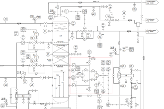
A piping and instrumentation diagram/drawing (P&ID) is a diagram in the process industry which shows the piping of the process flow together with the installed equipment and instrumentation.

P&ID Guidelines for Control Valves

P&ID Guidelines for Control Valves

The sample drawing presented here represents a typical arrangement generally used to represent control valves on P&ID. Depending on the projects legend sheets, control valves may be represented by globe or gate valves. Here a globe valve symbol is used. First of all a proper valve symbol should be selected to represent the control valve as per the project standards.

Generally, the control valve size is smaller than the corresponding line size. This change in diameter should be clearly indicated in the P&ID with reducer and expander.

Block valves should be provided upstream and downstream of the control valves in case of shutdown and maintenance.

A drain valve is normally provided between the control valve and upstream block valve. If the control valve is of ‘Fail Open’ type, this drain valve is sufficient to drain the piping segment. If the control valve is of ‘Fail Close’ or ‘Fail in Position’ type, then additional drain valve is required between the control valve and downstream block valve as shown in the sample drawing.

Normally, either a bypass or a handwheel is provided for control valves which are under continuous service. If two or more control valves are installed in parallel, bypass or handwheel is not required.

The choice between providing either a bypass or a handwheel for the control valve is made based on the size of the control valve. For control valves bigger than a certain size, provision of handwheel is preferred. For control valves smaller than certain size, provision of bypass with block valves is preferred.

For control valves on certain critical services, a spare control valve may be installed on the bypass of main control valve. This limiting control valve size between handwheel and bypass is specific for a project and may vary from one project to another.

If the control valve is equipped with a handwheel, then only the drain between control valve and upstream block valve is sufficient for draining by opening the control valve using handwheel.

Normally globe valve is selected as the bypass valve on the control valve as it allows better control with opening.

Additional details such as failure position, tightness class, # rating etc. are also indicated on the P&ID for control valves, as per the project standards.

All the guidelines given here are very general and may be modified as per specific requirements of any particular project.

Don't Miss Our Updates
Be the first to get exclusive content straight to your email.
We promise not to spam you. You can unsubscribe at any time.
Invalid email address
You've successfully subscribed !

Continue Reading

Multiple Thermowell Installations Problems
Field Instruments Mounting brackets
P&ID Guidelines for Pressure Safety Valves
P&ID Guidelines for Separator Vessels
Gas Detectors Installation Techniques
Installation and Maintenance of Control Valves
Share This Article
Facebook Whatsapp Whatsapp LinkedIn Copy Link
Share
Leave a Comment

Leave a Reply Cancel reply

Your email address will not be published. Required fields are marked *

Stay Connected

128.3kFollowersLike
69.1kFollowersFollow
208kSubscribersSubscribe
38kFollowersFollow

Categories

Explore More

Cable Trays Glossary
Instrument Tube Fitting Installation – Part 3
How Not to Install an Instrument and Wrong Practices
Flow Meter Installation Guidelines
Instrument Tube Fitting Installation – Part 2
Thermocouple Temperature Measurement Errors
Instrument Tube Fitting Installation – Part 1
P&ID Guidelines for Pumps Heat Exchangers

Keep Learning

Instrumentation Cables Questions Answers

Instrumentation Cables Questions & Answers

Cut-outs between Platforms or Grating for Field Instruments

Cut-outs between Platforms or Grating for Field Instruments

Slop Tank Level Transmitter Erection

Wrong Installation of Horn Type Radar Level Transmitter on Sloping Tank

Direct Mounting of Diaphragm Seals Level Transmitter

What are the Mounting Techniques of Diaphragm Seals?

DP transmitter with Manifold

Pressure Transmitter Manifolds

Magnetic Float Level Switch Principle

Magnetic Float Level Switch Installation Techniques

Instrumentation Cables Armor

Instrumentation Cables Armor

Hook-up Diagram for Pressure Gauge

What is Instrument Hook Up Diagram ?

Learn More

PID Controller Tuning

How to tune a PID Controller ?

Add On Instructions Programming – Analog Input Devices in Studio 5000

Welding Machine Fail in Dusty and Corrosive Areas

Welding Machine Fail in Dusty and Corrosive Areas

Electrical Machines Questions and Answers

DC Generators Characteristics Quiz

Interview Questions on Transformers

Electrical & Instrumentation QC Interview Questions

Identification of Equipment Standards

Identification of Equipment

Difference between LVDT and RVDT

Difference between LVDT and RVDT?

Electric Solenoid Actuators Principle

What is a Electric Solenoid Actuator ?

Follow US
All rights reserved. Reproduction in whole or in part without written permission is prohibited.
Welcome Back!

Sign in to your account

Username or Email Address
Password

Lost your password?