A Freewheeling diode also called as flyback diode. The freewheeling diode also called as snubber diode, commutating diode, freewheeling diode, suppressor diode, suppression diode, clamp diode, or catch diode. Its main purpose to eliminate flyback, which is the sudden voltage spike seen across an inductive load when its supply current is suddenly reduced or interrupted.
Let’s start with some physics. The voltage v across a coil having the inductance L is proportional to di/dt, the change of current flow over the time:
v = L ( di/dt )
Once a constant voltage v is applied to an inductor, a current starts to rise linearly at a rate of di in the time dt. In case v turns back to zero, also the change of current over the time becomes zero – with other words, the current i keeps to flow constantly through the coil at its actual value!
On the other hand, at a rapid change in current flow – e. g. when a switch interrupts the circuit – a high di/ dt occurs and as a result an extreme voltage spike v. At ignition coils, such high voltage peaks are desired for generating sparks.
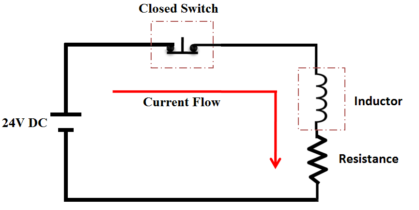
In its most simplified form with a voltage source connected to an inductor with a switch, we have 2 states available. In the first steady-state, the switch has been closed for a long time such that the inductor has become fully energized and is behaving as though it were a short (above Figure 1).
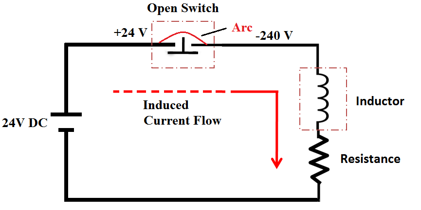
Current is flowing “down” from the positive terminal of the voltage source to its negative terminal, through the inductor. When the switch is opened (below Figure 2), the inductor will attempt to resist the sudden drop of current (dI/dt is large therefore V is large) by using its stored magnetic field energy to create its own voltage.
An extremely large negative potential is created where there once was positive potential, and a positive potential is created where there was once negative potential.
The switch, however, remains at the voltage of the power supply, but it is still in contact with the inductor pulling down a negative voltage. Since no connection is physically made to allow current to continue to flow (due to the switch being open), the large potential difference can cause electrons to “arc” across the air-gap of the open switch (or junction of a transistor). This is undesirable for the reasons mentioned above and must be prevented.
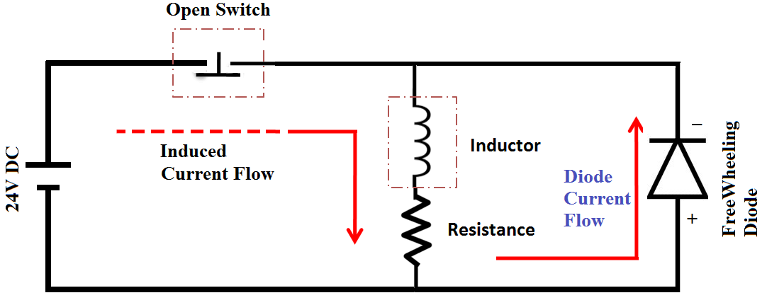
A flyback diode solves this starvation-arc problem by allowing the inductor to draw current from itself (thus, “flyback”) in a continuous loop until the energy is dissipated through losses in the wire, the diode and the resistor (below Figure 3).
When the switch is closed the diode is reverse-biased against the power supply and doesn’t exist in the circuit for practical purposes.
However, when the switch is opened, the diode becomes forward-biased relative to the inductor (instead of the power supply as before), allowing it to conduct current in a circular loop from the positive potential at the bottom of the inductor to the negative potential at the top (assuming the power supply was supplying positive voltage at the top of the inductor prior to the switch being opened).
The voltage across the inductor will merely be a function of the forward voltage drop of the flyback diode. Total time for dissipation can vary, but it will usually last for a few milliseconds.
In an ideal flyback diode selection, one would seek a diode which has very large peak forward current capacity (to handle voltage transients without burning out the diode), low forward voltage drop, and a reverse breakdown voltage suited to the inductor’s power supply.
Depending on the application and equipment involved, some voltage surges can be upwards of 10 times the voltage of the power source, so it is critical not to underestimate the energy contained within an energized inductor.
When used with a DC coil relay, a flyback diode can cause delayed drop-out of the contacts when power is removed, due to the continued circulation of current in the relay coil and diode.
When rapid opening of the contacts is important, a low-value resistor can be placed in series with the diode to help dissipate the coil energy faster, at the expense of higher voltage at the switch.
Schottky diodes are preferred in flyback diode applications for switching power converters, because they have the lowest forward drop (~0.2 V rather than >0.7 V for low currents) and are able to quickly respond to reverse bias (when the inductor is being re-energized). They therefore dissipate less energy while transferring energy from the inductor to a capacitor.
Why Induction at the opening of a contact
According to Lenz’s law, if the current through an inductance changes, this inductance induces a voltage so the current will go on flowing as long as there is energy in the magnetic field. If the current can only flow through the air, the voltage is therefore so high that the air conducts.
That is why in mechanically-switched circuits, the near-instantaneous dissipation which occurs without a flyback diode is often observed as an arc across the opening mechanical contacts.
Energy is dissipated in this arc primarily as intense heat which causes undesirable premature erosion of the contacts. Another way to dissipate energy is through electromagnetic radiation.
Similarly, for non-mechanical solid state switching (i.e., a transistor), large voltage drops across an unactivated solid state switch can destroy the component in question (either instantaneously or through accelerated wear and tear).