In addition to maximum (total) cable length and repeater count, a host of other details (Note 1) conspire to limit how any particular H1 segment is wired. To help engineers and technicians alike deal with these details, manufacturers often provide free segment design tool software to pre-validate a segment design on computer before purchasing components and installing them in the field.
Note 1 : Total device current draw, spur length versus number, intrinsic safety voltage and current limitations, etc.
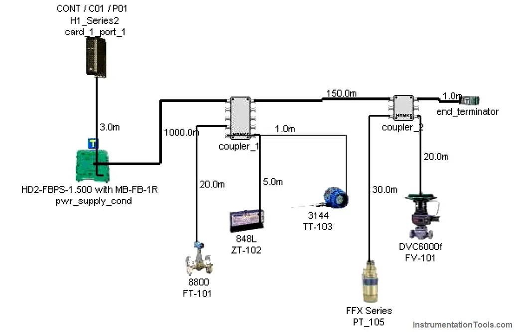
A screenshot taken from Emerson’s offering shows what a typical FF segment layout might look like:
A very nice feature of these segment design packages is their built-in database of FF components. Every time you “pick” a particular component to place in your simulated segment, the program references data for that device’s current draw and other electrical parameters relevant to the performance of the segment. Of course, each manufacturer will tend to feature their own devices more prominently, and so these software tools sometimes feel like a promotional advertisement. Despite the commercial aspect of their design, however, they are extremely useful in the planning stages of a FF network, and should be used whenever possible.
Another reason to use segment design tool software is to document the wiring of each FF segment. One of the casualties of the new Fieldbus paradigm is the traditional loop diagram (or “loop sheet”), the purpose of which is to document the signal wiring dedicated for each measurement and control loop. In FOUNDATION Fieldbus, the control “loop” is virtual rather than physical, being comprised of digital data sent between field instruments, the path of which being defined by the instruments’ programming. The only physical wiring entity to document in a FF system is the segment, and each segment most likely hosts more than one measurement and/or control loop. Unless and until a standardized documentation format is invented for Fieldbus network segments, the graphic image provided by segment design tool software is as good as anything.







In foundation fieldbus Design sagment which communication used from filed instruments to local module and local module(coupler) to main module?