Inst ToolsInst ToolsInst Tools
  • Courses
  • Automation
    • PLC
    • Control System
    • Safety System
    • Communication
    • Fire & Gas System
  • Instrumentation
    • Design
    • Pressure
    • Temperature
    • Flow
    • Level
    • Vibration
    • Analyzer
    • Control Valve
    • Switch
    • Calibration
    • Erection & Commissioning
  • Interview
    • Instrumentation
    • Electrical
    • Electronics
    • Practical
  • Q&A
    • Instrumentation
    • Control System
    • Electrical
    • Electronics
    • Analog Electronics
    • Digital Electronics
    • Power Electronics
    • Microprocessor
  • Request
Search
  • Books
  • Software
  • Projects
  • Process
  • Tools
  • Basics
  • Formula
  • Power Plant
  • Root Cause Analysis
  • Electrical Basics
  • Animation
  • Standards
  • 4-20 mA Course
  • Siemens PLC Course
Reading: Float Level Switch Working Principle Animation
Share
Notification Show More
Font ResizerAa
Inst ToolsInst Tools
Font ResizerAa
  • Courses
  • Design
  • PLC
  • Interview
  • Control System
Search
  • Courses
  • Automation
    • PLC
    • Control System
    • Safety System
    • Communication
    • Fire & Gas System
  • Instrumentation
    • Design
    • Pressure
    • Temperature
    • Flow
    • Level
    • Vibration
    • Analyzer
    • Control Valve
    • Switch
    • Calibration
    • Erection & Commissioning
  • Interview
    • Instrumentation
    • Electrical
    • Electronics
    • Practical
  • Q&A
    • Instrumentation
    • Control System
    • Electrical
    • Electronics
    • Analog Electronics
    • Digital Electronics
    • Power Electronics
    • Microprocessor
  • Request
Follow US
All rights reserved. Reproduction in whole or in part without written permission is prohibited.
Inst Tools > Blog > Animation > Float Level Switch Working Principle Animation

Float Level Switch Working Principle Animation

Last updated: December 18, 2018 6:38 am
Editorial Staff
Animation How It Works Level Measurement Switches
No Comments
Share
1 Min Read
SHARE

All float-operated liquid level switches operate on the buoyancy principle: “the buoyant force acting on an object is equal to the mass of liquid displaced by the object”.

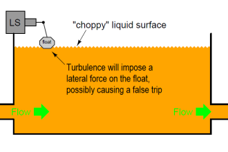
As a result, the partially submerged float moves with the level of the liquid in the vessel. Floats are most-commonly used for narrow level differential applications such as high level and low level alarms.

Level Float Switch Working Principle Animation

The Float level switches use a float containing an internal magnet and a stem with an encapsulated, hermetically-sealed reed switch.

As the float rises and falls with the liquid level, its internal magnet causes the switch circuit to open and close. The non-magnetic stem isolates it from the process.

Float Level Switch Working

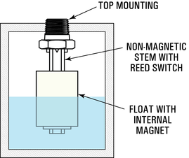
Float-type level controls are available for top mounting, side mounting and external chamber applications. Single and multi-level models are used to monitor preset liquid or liquid interface levels.

Optional internal thermostats and RTD’s also monitor process temperature within the same sensor.

Also See: Ultrasonic Level Switch Working Animation
Don't Miss Our Updates
Be the first to get exclusive content straight to your email.
We promise not to spam you. You can unsubscribe at any time.
Invalid email address
You've successfully subscribed !

Continue Reading

Basics of Globe Valves
Pitot Tube Working Principle
Oscillating Piston Flow Meters Working Principle
What is ON/OFF Valve ?
Load Cell Working Principle
DP Level Transmitter Calibration for Diaphragm Seal with Capillary
Share This Article
Facebook Whatsapp Whatsapp LinkedIn Copy Link
Share
Leave a Comment

Leave a Reply Cancel reply

Your email address will not be published. Required fields are marked *

Stay Connected

128.3kFollowersLike
69.1kFollowersFollow
210kSubscribersSubscribe
38kFollowersFollow

Categories

Explore More

Remote Seal Differential Pressure Transmitters Principle
Online Simulation
Radar and Ultrasonic Level Transmitter Practical Problems Troubleshooting
What is Seal-in Circuit ?
Turbine Flow Meters Animation
Level Transmitter Animation
Open and Closed Tank Level Calculations
Proximity switches Circuit Diagram Operation

Keep Learning

Oval Gear Flow Meter Principle

Oval Gear Flow Meters – Principle, Advantages, Animation

level-transmitter-calibration-procedure

Level Transmitter Calibration Procedure

Reflex Level Gauge Parts

What is Reflex Level Gauge?

Sealed Bellows Temperature Sensors

Bellows Pressure Sensors Working Principle Animation

Calibration Procedure of displacer type Level transmitter

Calibration of Displacer Level Transmitter

Rotary Level Switch Working Principle Animation

Rotary Level Switch Working principle Animation

Level Measurement using DP Transmitters - Open Tank

Open Tank Level Measurement using DP Transmitters Animation

Potentiometer Animation

Potentiometer Working Principle Animation

Learn More

PRV

Direct-actuated Safety and Relief Valves

Thermowell Problems

Thermowell Problems

Comparison Instructions in PLC Programming

Comparison Instructions in PLC Programming

PLC ON DELAY TIMER FUNCTION

#6 PLC Best Practices – Validate Timers and Counters

5-Port-2-Position-Valve-Animation

5 Port 2 Position Valve Working Principle

electronics-questions-and-answers

Electronics Questions & Answers

Applications of Electrical Conduit System

What is an Electrical Conduit? – Types – How to Choose?

Basic Terms used in SIL Verification

Basic Terms used in SIL Verification

Menu

  • About
  • Privacy Policy
  • Copyright

Quick Links

  • Learn PLC
  • Helping Hand
  • Part Time Job

YouTube Subscribe

Follow US
All rights reserved. Reproduction in whole or in part without written permission is prohibited.
Welcome Back!

Sign in to your account

Username or Email Address
Password

Lost your password?