This article discusses the PLC program “Flip-Flop Lamp” using the XG-5000 PLC software. This Flip-Flop program has 2 lights that will light up alternately at adjustable time intervals. The quantity of repetitions of the lights on can be adjusted. Lights 1 and 2 will stop lighting when the quantity of repetitions has been reached. The system can only be Run if the “Set Value” parameter of the timer interval and the “Set Value” parameter of the quantity of repetitions have been Set. This Flip-Flop program has a Start and Stop button to turn the system On and Off, and a Trigger button to Run the system.
Flip-Flop PLC Programming
Buttons used:
- The START (P00000) button is used to turn ON the system.
- The STOP (P00001) button is used to turn OFF the system.
- The TRIGGER button (P00002) is used to RUN the system.
SYSTEM ON (Standby)
When the START button (P00000) is Pressed, the system will be ON in the “Standby” state and when the STOP button (P00001) is Pressed, the system will be OFF.
Before the system is Run, the “Set Value” Timer parameter TIMER1 (T0000) & TIMER2 (T0001) in the memory word SV_TIMER1 (D00002) & SV_TIMER2 (D00003) must be set. The Parameter “Set Value” of repetitions can be Set on the word memory SV_LOOP (D00000).
SYSTEM RUNNING
When the TRIGGER button (P00002) is Pressed, the system will Run.
Lamp 1 LAMP1 (P00043) will turn ON according to the “Set Value” time that has been set in the word memory SV_TIMER1 (D00002).
Next, Lamp 2 LAMP2 (P00044) will turn ON according to the “Set Value” time that has been set in the memory word SV_TIMER2 (D00003).
Lamp 1 LAMP1 (P00043) and Lamp 2 LAMP2 (P00044) will turn ON alternately with repetitions according to the “Set Value” that has been set in the memory word SV_LOOP (D00000).
The system will Stop if the quantity of repetitions has been reached.
Addressing
| Comment | Input (I) | Output (Q) | Memory Word | Memory Bits | Timer |
| START | P00000 | ||||
| STOP | P00001 | ||||
| TRIGGER | P00002 | ||||
| LAMP1 | P00043 | ||||
| LAMP2 | P00044 | ||||
| TIMER1 | T0000 | ||||
| TIMER2 | T0001 | ||||
| SYSTEM_ON | M00000 | ||||
| IR_FLIP_FLOP | M00001 | ||||
| SV_LOOP | D00000 | ||||
| PV_LOOP | D00001 | ||||
| SV_TIMER1 | D00002 | ||||
| SV_TIMER2 | D00003 |
Lights with Adjustable Timers PLC Programming
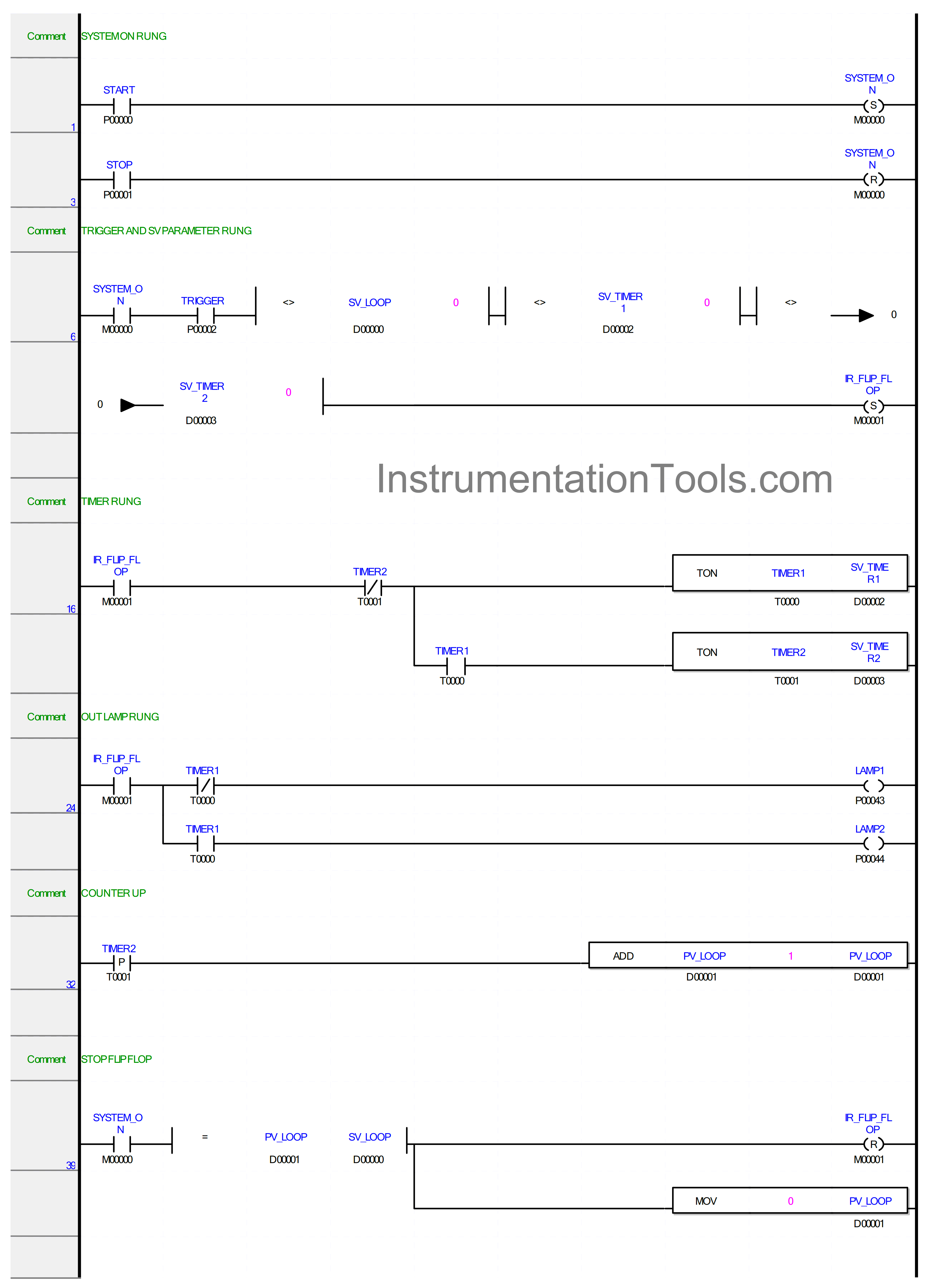
RUNG 1
In this Rung, the memory bit SYSTEM_ON (M00000) changes to the HIGH state if the START button (P00000) is Pressed. Because it uses the SET Coil Instruction, the memory bit SYSTEM_ON (M00000) will remain in the HIGH state even though the START (P00000) button has been Released.
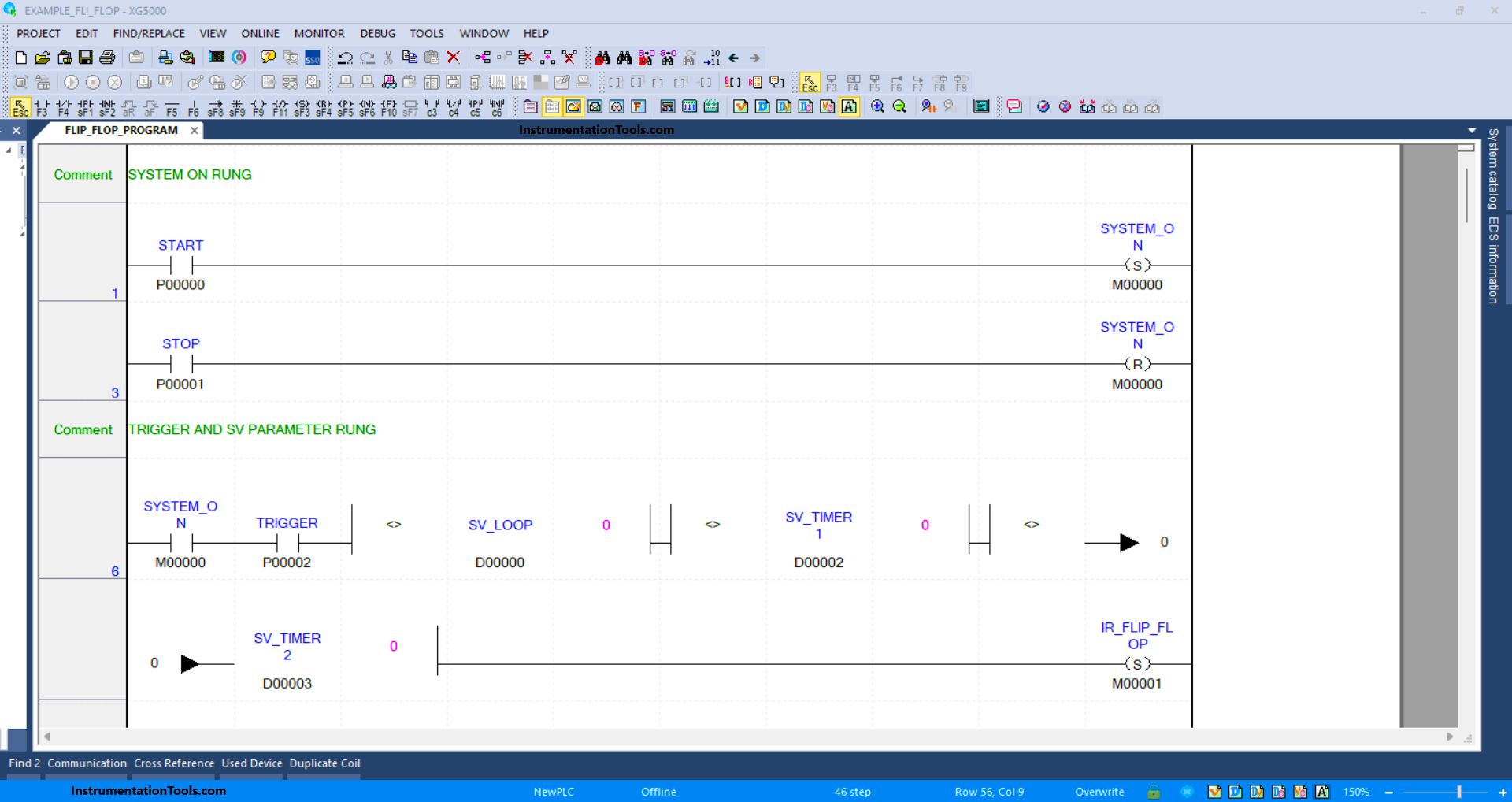
RUNG 3
Because it uses the RESET Coil Instruction, the memory bit SYSTEM_ON (M00000) will be in the LOW state if the STOP (P00001) button is Pressed.
RUNG 6
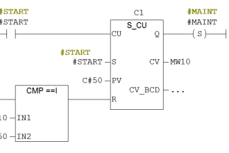
In this Rung, the memory bit IR_FLIP_FLOP (M00001) will become the HIGH state if the NO contact of memory bit SYSTEM_ON (M00000) in the HIGH state and the TRIGGER (P00002) button is Pressed and the value in the memory word SV_TIMER1 (D00002), SV_TIMER2 (D00003) and SV_LOOP (D00000) is not equal to zero “0”.
Because it uses the SET Coil Instruction, the memory bit SYSTEM_ON (M00000) will remain in the HIGH state even though the TRIGGER (P00002) button has been Released.
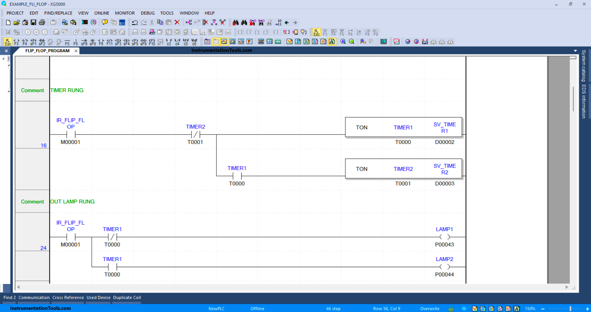
RUNG 16
In this Rung, if the NO contact of memory bit IR_FLIP_FLOP (M00001) in the HIGH state, then Timer TIMER1 (T0000) will start counting. When Timer TIMER1 (T0000) finishes counting, the NO contact of Timer TIMER1 (T0000) will be in the HIGH state and Timer TIMER2 (T0001) will start counting.
When Timer TIMER2 (T0001) has finished counting, Timer TIMER1 (T0000) and TIMER2 (T0001) will be OFF, because the NC contact of Timer TIMER2 (T0001) in the HIGH state.
RUNG 24
In this Rung, if the NO contact of the memory bit IR_FLIP_FLOP (M00001) in the HIGH state, then the Output LAMP1 (P00043) becomes ON. The Output LAMP1 (P00043) will be OFF if NC contact of
Timer TIMER1 (T0000) in HIGH state.
Output LAMP2 (P00044) will be ON if the NO contact of Timer TIMER1 (T0000) in the HIGH state.
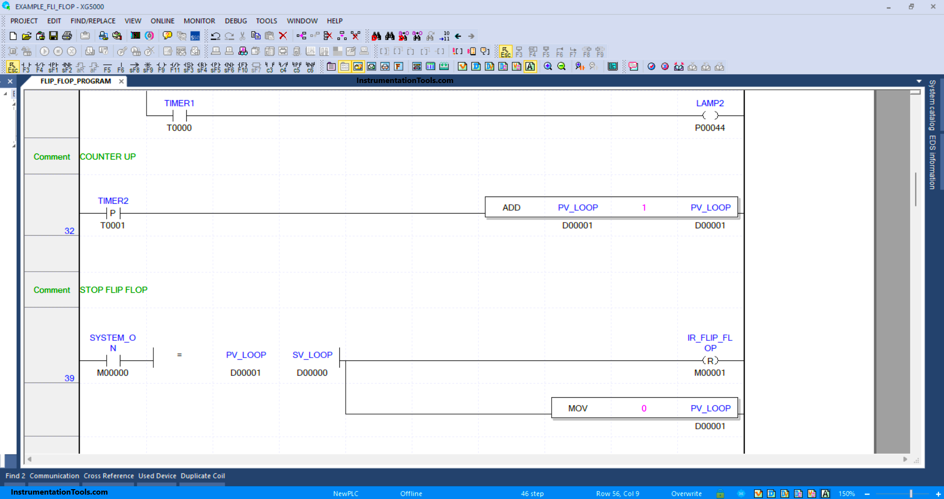
RUNG 32
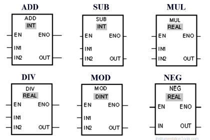
In this Rung, if the NO contact of the memory bit TIMER2 (T0001) in the HIGH state, then the value in memory word PV_LOOP (D00001) will increase (+1), because it uses the ADD instruction.
RUNG 39
In this Rung, if the NO contact of memory bit SYSTEM_ON (M00000) in the HIGH state and the value in memory word PV_LOOP (D00001) is equal to SV_LOOP (D00000), then the memory bit IR_FLIP_FLOP (M00001) becomes in the LOW state and the value in memory word PV_LOOP (D00001) will be zero “0”, because the MOV instruction moves the zero value “0” to memory word PV_LOOP (D00001).
Read Next:
- PLC 1 Button To Activate 4 Different Machines
- Vijeo Designer software Import and Export
- FactoryTalk View Studio Import and Export
- System Architecture in Industrial Automation
- Structured Text vs. Instruction List Languages


I see this as more of an advertisement of how to use as many different obtuse methods as possible,
If you are just trying to demonstrate a Flip/Flop, you should be able to do it with less than rungs.
If you have been doing this as long as I have, you know to use economy in your code. Each line adds up to execution time, which increases scan times.
Keep your programs as simple as possible, document your code so that a 5th grader could follow it, and save the bells and whistles for where you need them.