Inst ToolsInst ToolsInst Tools
  • Courses
  • Automation
    • PLC
    • Control System
    • Safety System
    • Communication
    • Fire & Gas System
  • Instrumentation
    • Design
    • Pressure
    • Temperature
    • Flow
    • Level
    • Vibration
    • Analyzer
    • Control Valve
    • Switch
    • Calibration
    • Erection & Commissioning
  • Interview
    • Instrumentation
    • Electrical
    • Electronics
    • Practical
  • Q&A
    • Instrumentation
    • Control System
    • Electrical
    • Electronics
    • Analog Electronics
    • Digital Electronics
    • Power Electronics
    • Microprocessor
  • Request
Search
  • Books
  • Software
  • Projects
  • Process
  • Tools
  • Basics
  • Formula
  • Power Plant
  • Root Cause Analysis
  • Electrical Basics
  • Animation
  • Standards
  • 4-20 mA Course
  • Siemens PLC Course
Reading: Flapper Nozzle Questions
Share
Font ResizerAa
Inst ToolsInst Tools
Font ResizerAa
  • Courses
  • Design
  • PLC
  • Interview
  • Control System
Search
  • Courses
  • Automation
    • PLC
    • Control System
    • Safety System
    • Communication
    • Fire & Gas System
  • Instrumentation
    • Design
    • Pressure
    • Temperature
    • Flow
    • Level
    • Vibration
    • Analyzer
    • Control Valve
    • Switch
    • Calibration
    • Erection & Commissioning
  • Interview
    • Instrumentation
    • Electrical
    • Electronics
    • Practical
  • Q&A
    • Instrumentation
    • Control System
    • Electrical
    • Electronics
    • Analog Electronics
    • Digital Electronics
    • Power Electronics
    • Microprocessor
  • Request
Follow US
All rights reserved. Reproduction in whole or in part without written permission is prohibited.
Inst Tools > Blog > Practical Questions > Flapper Nozzle Questions

Flapper Nozzle Questions

One of the most basic components of a pneumatic instrument is the so-called flapper nozzle, or baffle nozzle assembly.

Last updated: September 9, 2020 5:17 pm
Editorial Staff
Practical Questions
No Comments
Share
2 Min Read
SHARE

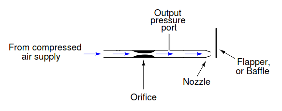
One of the most basic components of a pneumatic instrument is the so-called flapper/nozzle, or baffle/nozzle assembly. It consists of two restrictions to air flow, one within a tube (the orifice) and the other at the end of a tube (the nozzle).

The flapper, or baffle, is nothing more than a flat piece of metal in close proximity to the nozzle tip. These mechanisms serve as extremely sensitive position detectors, generating a pneumatic pressure output signal that varies with flapper (baffle) position:

Flapper Nozzle

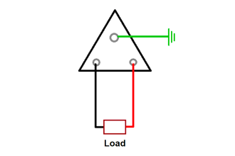
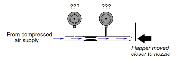
Suppose that two pressure gauges were installed along the length of the tube, one upstream of the orifice and the other downstream of the orifice, like this:

Pressure Gauge upstream of the orifice

Qualitatively speaking, what would these two pressure gauges indicate? Assume that the air supply is regulated by a pressure regulator, and so remains at a constant pressure. Would the two pressure gauges indicate the same amount of pressure? Would one of them indicate a higher pressure than the other? Explain your answer.

If the flapper (baffle) is brought closer to the nozzle, the nozzle will become more restrictive to air flowthrough it. What effect will this have on the two pressure gauge indications in this flapper/nozzle system?

Baffle Nozzle

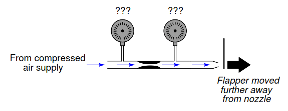
If the flapper travels further away from the nozzle, what effect will it have on the two pressure gauges’ indications?

Flapper Moved Away from Nozzle

Answer:

The pressure gauge downstream of the orifice will indicate a lower pressure than the gauge upstream of the orifice. Moving the flapper closer to the nozzle increases the downstream pressure, while moving the flapper away from the nozzle decreases the downstream pressure.

Follow-up question: sketch a schematic diagram for an electrical circuit analogous to this pneumatic“circuit” formed by the pressure source, orifice, nozzle, and flapper.

Share your answers with us through the below comments section.

Read Next:

  • Pneumatic Relay
  • Pneumatic Elements
  • Flapper-Nozzle Regulator
  • Single Block and Bleed Valve

Credits: Tony R. Kuphaldt

Don't Miss Our Updates
Be the first to get exclusive content straight to your email.
We promise not to spam you. You can unsubscribe at any time.
Invalid email address
You've successfully subscribed !

Continue Reading

Calculate the Magnitude of Hydrostatic Pressure
Programmable Logic Controller (PLC) Questions and Answers – 3
Three-valve Manifold on Remote Seal DP Transmitter
Diagnosing Electric Motor Circuit
DP Transmitter Located 10 feet Beneath the Vessel
Define Normal Status of a Process Switch ?
Share This Article
Facebook Whatsapp Whatsapp LinkedIn Copy Link
Share
Leave a Comment

Leave a Reply Cancel reply

Your email address will not be published. Required fields are marked *

Stay Connected

128.3kFollowersLike
69.1kFollowersFollow
210kSubscribersSubscribe
38kFollowersFollow

Categories

Explore More

Determine the Temperature of 3 Wire RTD
PLC Switch Actuation Status
How to Connect Proximity Switch (Sink Type) to Make LED ON ?
DP transmitter Elevated 10 Feet above the Vessel
Calculate LRV and URV for 4-20 mA Loop-powered DP Transmitter
Instrument Lab Exercise – Ranging and Manometer Usage
Resistance Temperature Detector (RTD) Questions – 1
Identify the Purpose of Flow Ratio Controller

Keep Learning

Programmable Logic Controller (PLC) Questions and Answers

Programmable Logic Controller (PLC) Questions and Answers – 2

AB PLC Temperature Switch

Programmable Logic Controller (PLC) Questions and Answers – 17

Fisher model 546 I to P transducer

Fisher model 546 I/P transducer

How Much Pressure indicated by Micromanometer

How Much Pressure Indicated by Micromanometer?

Suppose the lamp refuses to light up

Indentify Faults in Simple Lamp Circuit including Failed Wires

Double Block and Bleed Valves Opening or Closing Sequence

Double Block and Bleed Valves Opening or Closing Sequence

Pitot tube

Pitot Tube Flowmeter Calculations

Inductive proximity switches

How to Connect Proximity Switch (Source Type) to Make LED ON ?

Learn More

What is Wellhead Control Panel?

Relation Control

Relation Control System

Difference Between MCB and MCCB

Difference Between MCB and MCCB

Metal tube Variable Area Flowmeters Principle

Metal Tube Variable Area Flow Meters Principle

SIS PFD - Safety Instrumented System

SIS PFD – Safety Instrumented System

How to Control VFD with PLC using Ladder Logic

Electrical Conductivity Meter

What is the Application of Electrical Conductivity Meter?

Magnetostrictive instruments

Magnetostrictive Level Measurement

Menu

  • About
  • Privacy Policy
  • Copyright

Quick Links

  • Learn PLC
  • Helping Hand
  • Part Time Job

YouTube Subscribe

Follow US
All rights reserved. Reproduction in whole or in part without written permission is prohibited.
Welcome Back!

Sign in to your account

Username or Email Address
Password

Lost your password?