Regarding the Programming Engineers, there is always an idiom stating that “It is not about your code result, it is always about how did you make it.”
So, today we are going to enhance our programming skills by learning a new tool that will help us to build a (first input first output) register.
But before we are getting started, we need to know why we need such instruction? and when are we supposed to use it? so clear your mind and stay tuned.
FIFO is a structure used in hardware or software applications when you need to buffer data.
Basically, you can think about a FIFO as a bus queue, the people that arrive first is the one who catches the bus first.
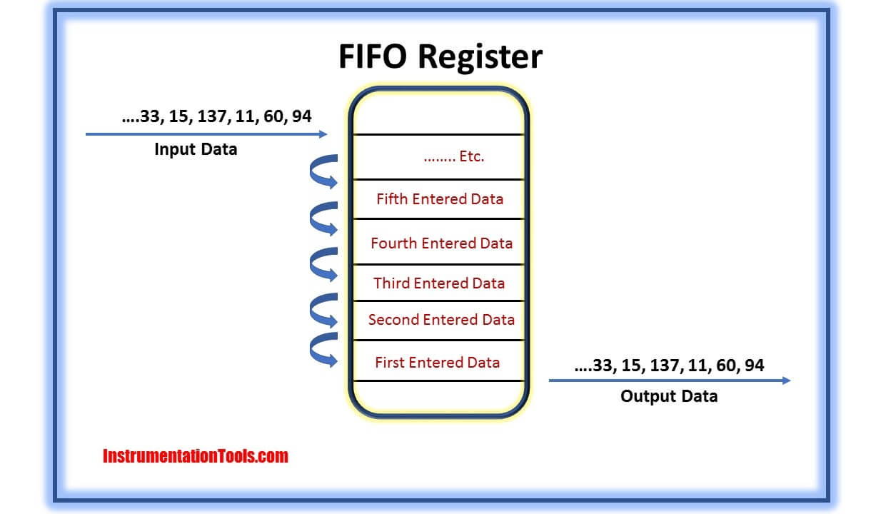
Sometimes your input data and field signals are being done faster than the system outputs that you have to make, so in order to handle such a situation you have to make an instruction that slows down the flow of input data and at the same time you have to store these data safely and by its turn.
Simply that is what a FIFO block can do, it outputs the oldest entry of the “FIFO” table as function value then the number of entries is decremented by one and If there are still entries in the table, these are shifted down.
First of all, you have to understand that this operation needs two instructions.
By pressing the right click on program blocks you can choose Add new block.
Then we have to configure the database as illustrated in the next figure. Fig. (4)
As we can see in the next figure Fig. (5), the first network is responsible for unloading our FIFO table by activating M0.0 automatically the data in turn will be transmitted to MW2.
And for the second network, we can see that it is responsible for loading the table by activating M1.0 automatically the data in MW4 will take its turn into the FIFO table.
Note: the word (P#DB1.DBX0.0) stands for the start address of your table.
If you liked this article, then please subscribe to our YouTube Channel for Electrical, Electronics, Instrumentation, PLC, and SCADA video tutorials.
You can also follow us on Facebook and Twitter to receive daily updates.
Learn an example PLC program to control a pump based on level sensors using ladder…
In the PLC timer application for security camera recording, when motion is detected then camera…
In this example, we will learn batch mixing with PLC ladder logic program using timer…
This PLC example on manufacturing line assembly is an intermediate-level PLC program prepared for the…
In this article, you will learn the PLC programming example with pushbutton and motor control…
This article teaches how to convert Boolean logic to PLC programming ladder logic with the…


