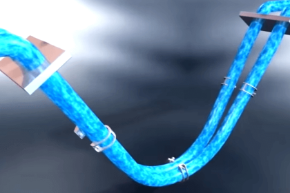
The measurement of flow in a plant is important for the control of the process and for troubleshooting problems that may occur. In some cases, an approximate flow rate is acceptable for control purposes so a relatively inexpensive instrument is acceptable.
In other situations, greater accuracy is required which will require a more sophisticated instrument to cost more. There are a variety of flow measuring devices available but not all are suitable for acid plant service.
Differential Pressure Devices
Flow devices producing a differential pressure signal, have a reputation for accuracy, simplicity, and reliability.
Some differential pressure devices are orifice plates, venturi tubes, flow nozzles, annubars, wedge flow meters, etc. The most common types found in sulphuric acid plant application are described.
Annubar
An annubar produces a differential pressure (DP) signal proportional to the square of the flow rate in accordance with Bernoulli’s theorem. This signal has two components; the high pressure (PH) and the low pressure (PL).
The high pressure is produced by the impact of the velocity profile on the sensor. The velocity profile results in a corresponding impact pressure profile. Multiple sensing ports located on the front of the sensor, sense the impact pressure profile. Inside the high-pressure chamber, the average velocity pressure is maintained by the proportionality of the sensing port diameters to the chamber cross-sectional area.
The velocity profile continues around the sensor and creates a low-pressure profile. The low-pressure profile is sensed by ports, located downstream and opposite the high-pressure ports. Working on the same principle as the high-pressure side, an average low pressure is maintained in the low-pressure chamber. The resulting differential pressure is transmitted through the instrument head to a differential pressure flow meter.
Orifice Plates
A concentric, sharp-edged orifice plate is the simplest and least expensive of the differential head meters. The orifice plate constricts the flow of a fluid to produce a differential pressure across the plate. The result is a high pressure upstream and a low pressure downstream that is proportional to the square of the flow velocity.
The disadvantage of an orifice plate is it usually produces a greater overall pressure loss than other differential pressure devices. An advantage of this device is that cost does not increase significantly with pipe size.
Elbow Meters
As a fluid passes through a pipe elbow, the pressure at the outside radius of the elbow increases due to centrifugal force. If pressure taps are located at the outside and inside of the elbow, a reproducible measurement can be made.
Elbow flow meters are inexpensive and do not introduce any obstructions to the flow of liquid.
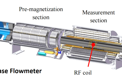
Magnetic Flow Devices
The operating principle of the magnetic flow tube is based on Faraday’s law of electromagnetic induction, which states that a voltage will be induced in a conductor moving through a magnetic field.
Faraday’s Law: E = kBDV
The magnitude of the induced voltage (E) is directly proportional to the velocity of the conductor (V), conductor width (D), and the strength of the magnetic field (B).
Field coils placed on opposite sides of the flow tube generate a magnetic field. As the conductive process liquid moves through the field with average velocity V, electrodes sense the induced voltage.
The flowmeter must be completely flooded at all times to obtain an accurate measurement of flow. Installation in vertical pipes where the flow is going up is ideal. If the flowmeter and piping are drained during shutdowns, this should be specified to the vendor so appropriate measures can be taken to avoid damage to the flowmeter due to overheating.
Mass Flow Meters
True mass flowmeters measure the mass flow directly rather than the volumetric flow and density and then calculate the mass flow from the two measured values.
Coriolis Meters
The Coriolis meter uses an obstructionless U-shaped tube vibrating at its natural frequency as the fluid passes through it. The tube twists as a result of the flowing fluid and the angular movement of the tube created by the vibration.
Sensors measure the amount of twist and this is proportional to the mass flow rate through the pipe. Coriolis meters operate independently of liquid density, pressure, and viscosity.
Thermal Meters
Thermal meters are commonly applied to gas streams only where the transfer of heat to and from the stream is a usual element of the metering process.
Measuring the heat transfer supplies data from which a mass flow rate may be calculated. Thermal meters operate independently of density, pressure, and viscosity.
Variable Area Devices
Variable area devices, more commonly known as rotameters, are typically made from a tapered glass tube that is positioned vertically in the fluid flow. A flow that is the same size as the base of the glass tube rides upward in relation to the amount of flow.
Because the tube is larger in diameter at the top of the glass than at the bottom, the float resides at the point where the differential pressure between the upper and lower surfaces balances the weight of the float. In most cases, the flow rate is read directly from a scale inscribed in the flow tube but transmitting rotameters are available.
Ultrasonic
Ultrasonic flow meters utilize sound waves to determine the flow rate of fluids. Pulses from a piezoelectric transducer travel through a moving fluid at the speed of sound and provide an indication of fluid velocity. Two different methods are currently employed to establish this velocity measurement; transit-time and Doppler methods.
Ultrasonic meters have several advantages, including freedom from obstructions in the pipe and negligible cost sensitivity with respect to pipe diameter. However, their performance is sensitive to flow conditions.
Transit-Time
The transit-time method uses two opposing transducers which are mounted at a 45-degree angle to the direction of flow. The speed of sound from the upstream transducer to the downstream transducer represents the inherent speed of sound plus a contribution from the fluid velocity.
A simultaneous measurement is taken in the opposite direction which represents the speed of sound minus the fluid velocity. The difference between these two values is representative of the fluid velocity which is linearly proportional to the flow rate.
This method works well where the fluid is free of entrained gas or solids which can scatter the sound waves traveling between the transducers.
Doppler
This type of ultrasonic meter uses two transducers mounted in the same case on one side of the pipe. An ultrasonic sound wave of constant frequency is transmitted into the fluid by one transducer. Solids or bubbles within the fluid reflect the sound back to the receiver element.
The Doppler principle states that there will be a shift in apparent frequency or wavelength when there is relative motion between the transmitter and receiver. Within the Doppler flow meter, the relative motion of the reflecting bodies suspended within the fluid tends to compress the sound into shorter wavelength (high frequency).
This new frequency measured at the receiving element is electronically compared with the transmitted frequency to provide a frequency difference that is directly proportional to the flow velocity in the pipe. In contrast to the transit-time method, Doppler ultrasonic meters required entrained gases or suspended solids within the flow to function correctly.
Flow Instruments Accuracy and Repeatability
| Instrument | Accuracy/Repeatability | Installation | References | Remarks |
| Annubar | ± 1% over a flow turndown of greater than 10 to 1, independent of Reynold’s number. ± 0.1% repeatability | 7 PDU 3 PDD (single elbow flow disturbances) | Dieterich Standard Diamond II Annubar | Relatively low pressure drop |
| Orifice Plate | ± 2-4% of full scale | 10-30 PDU 4-8 PDD (dependent on flow disturbances and orifice b ratio) | Relatively high pressure drop | |
| Coriolis | ± 0.2% of rate | No requirements for upstream of downstream pipe diameters | Micro Motion Model D65 Rosemount Technical Data Sheet 3031 | Can also be used to measure density of fluid |
| Magnetic | ± 0.5% of rate from 1 to 30 ft/s ± 0.005% from low-flow cut-off to 1.0 ft/s | 5 PDU 3 PDD butterfly valves not recommended immediately upstream or downstream | Rosemount Model 8701 | Grounding rings required with lined or not conductive process piping. Pipe must be running full. |
| Elbow | ± 5-10% of full scale | 30 PDU | Rosemount Technical Data Sheet 3031 | Suitable for liquid flow only. Typically, there will be insufficient pressure differential generated in gas service. |
| Thermal | ± 2% of full scale | No requirements for upstream or downstream pipe diameters | Rosemount Technical Data Sheet 3031 | Suitable for gas flow measurement only. |
| Variable Area | ± 2% of full scale | No requirements for upstream or downstream pipe diameters | Rosemount Technical Data Sheet 3031 | |
| Ultrasonic | Transit-Time: ± 1% of rate Doppler: ± 3% of rate | 5-30 PDU | Rosemount Technical Data Sheet 3031 |
Applications of Flow Instruments
The following is a list of typical acid plant services for flow meters and the recommended instrument to measure the flow.
| Service | Instrument | Remarks |
| Sulphuric Acid | Magnetic | Use if accurate measurement of flow rate is required. Advantage is no additional pressure losses are introduced. The probe type magnetic flow meters should not be used. These were replaced by the flowtube type. |
| Orifice | Can be used where accuracy is not important (ie. for alarm or interlock function). Additional pressure drop is introduced to the system. Material of construction is typically Lewmet (Lewis Pumps). | |
| Ultrasonic | Used primarily as a diagnostic tool for situations where a flowmeter has not been installed. Suitable only for liquid flow measurement. | |
| Elbow | Can be used where accuracy is not important (ie. for alarm or interlock function). Does not introduce any additional pressure drop to the system. | |
| Liquid Sulphur | Wedge | Proven reliable and accurate. Diaphragm seals and a custom steam jacket are required. |
| Liquid SO2 | Coriolis | Suitable for use in commerce (i.e. weighing for sales purposes) |
| Process Gas | Annubar | Used to measure flow at plant inlet, blower discharge and stack. Prone to plugging if not maintained properly. |
| Thermal | Should be considered as a replacement for annubars in location where annubars continually plug. | |
| Water | Annubar | Used where accuracy is required. |
| Orifice | Can be used where accuracy is not important (ie. for alarm or interlock function). Additional pressure drop is introduced to the system. | |
| Rotameters | For small flows rates, such as acid dilution or make-up water service. | |
| Steam | Orifice | Used in saturated or superheated steam service. Typically, used as part of a multi-point level control for the steam drum level. |
If you liked this article, then please subscribe to our YouTube Channel for Instrumentation, Electrical, PLC, and SCADA video tutorials.
You can also follow us on Facebook and Twitter to receive daily updates.
Read Next:
- Flow Meter Calibration
- Averaging Pitot Tube
- Flow Meter Verification
- MPFM Working Principle
- Flow Transmitter Questions


Title need to be modified, to contain something relating to Flow.
ex “Flow Measurement Field Instrument – Selection, Principle & Application”