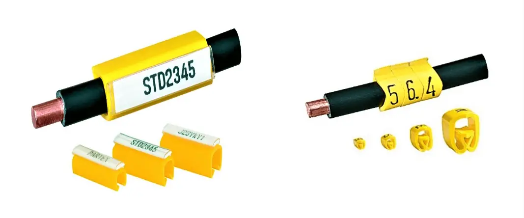
Ferrules are identification labels provided for every wire terminations in an instrument, equipment, or electrical/instrumentation control panels.
These tube-shaped sleeves can be inserted easily on each individual wire in a multi-core cable.
In earlier days fixed digits/letters are used as ferrules, but now Instrumentation engineers/technicians prints out desired ferrules by using a ferrule printing machine.

The numbers/ letters on the ferrules will be given as per the approved electrical hook up or loop diagrams.
This helps technicians to easily identify a particular loop/wiring from a series of terminal blocks and to troubleshoot the desired terminal connection.
Separate numbers on the ferrules distinguish the positive and negative polarities of wires, thus ensure the polarity protection of the instrument.
As a wire is connected on its both ends, it is quite useful to use a cross reference method for wire identification.
Unlike normal ferruling methods, cross ferruling gives information about the wire source as well as the destination, details about the Installation area, Panel, Junction Box, Terminal, and Polarity.
Structure of a typical Cross ferrule tag is shown below.
With all this information on a cross ferrule, technical personal get a clear idea of the loop wiring and are able to do the job very efficiently.
The above figure shows a typical loop diagram for a two-wire transmitter.
An intermediate JB is provided in between the control and field sides.
Each wire is provided with cross ferrules on both ends.
As shown in the above figure, Cross ferruling is used in between field – JB, and JB – Marshaling panels.
Each ferrule at the terminations gives a clear idea of where the other end is connected.
In the above image, all wires connected to the MCB’s are provided with labelling. It will help us to locate the respective inputs and outputs and helps us to trace the wires and troubleshooting will be easier.
Author: Visal KA
The conveyor sorting machine is widely used in the packing industries using the PLC program…
Learn the example of flip-flop PLC program for lamps application using the ladder logic to…
In this article, you will learn the STAR DELTA programming using PLC controller to start…
Lube oil consoles of rotary equipment packages in industrial process plants are usually equipped with…
Rotating equipment packages such as pumps, compressors, turbines need the lube oil consoles for their…
This article explains how to blink lights in ladder logic with a detailed explanation video…