Failsafe wiring practice is one of those topics that separates control system designers and electricians from other technical specialties. This is one of the areas that show up as problems if the design/installation team are not normally controls oriented.
This is also an area that causes a lot of rework on the part of the installers and the integrators when they meet during checkout onsite because it requires a lot of crosstalk in order to get in sync.
To enter a discussion of the merits of failsafe wiring, we need to come to an understanding of some of the basics terms:
The term normal operating condition should not be confused with the terms normally open (N.O.) or normally closed (N.C.).
Normal operating conditions are those in effect with the equipment running normally, and the process variable being measured is within tolerance.
Turning the equipment off, having the process variable go out of tolerance, or having any other component in the system fail will cause a loss of voltage (logical zero) at the annunciator or PLC, causing the alarm to be generated.
Note that such an alarm does not necessarily indicate that an alarm condition exists in the process (e.g., tank level too high), but that either the alarm condition exists or the alarm condition is no longer being monitored.
In the below circuit, a motor will start or stop based on an operator pressing the spring-loaded start or stop push buttons.
The operator presses the start button, the relay energizes, and then the operator can release the button as the relay has sealed a set of contacts around the push button.
If, however, the tank level is not in range, the motor starter coil will not energize because the level switches will not permit current to flow to the starter coil, and the motor will not start. If, after the motor starts, the level subsequently changes out of range, the relay will de-energize.
The motor will not restart, even if the level returns to normal, until the operator presses the button.
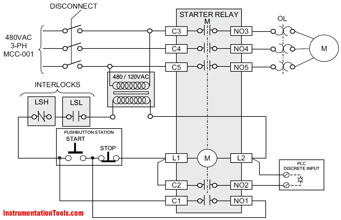
This circuit shown in Above Figure possesses all the key elements of a failsafe circuit. The end device operates only under prescribed process conditions and prescribed electrical conditions.
If anything happens to the power supply or any other part of the circuit, rendering it inoperable, the relay de-energizes, and an alarm is generated.
The only circumstance that would cause this circuit to fail in its function are mechanical problems, with either the relay contacts fusing together (which is rare now that most relays are encased and better protected from moisture) or the level switches failing to respond to changes in head pressure (level) as they are designed to do.
Most of the time, failsafe circuits use normally open contacts for interlock chains. In the case discussed above, however, a set of normally closed contacts was properly used.
This was proper because the level switches used here are dumb unpowered, non-electronic switches that switch the state of their outputs strictly based on pressure.
As the level in the tank rises, so does the pressure at the sensing point, which is fed to each switch via tubing. The increased pressure causes a bellows to inflate inside the switch body.
Eventually, the bellows inflates to a point where it exerts enough force on a contact set to overcome its mechanical reluctance (a mechanical setting that can be adjusted, or tuned, to a particular pressure), and the switch activates.
So using one switch as a low level switch and another as a high level switch depends simply on where you mount the switches and how you adjust their response to pressure changes.
The fact that the switch has a Form-C contact set allows the same model switch to be configured for failsafe operation, using the N.C. set for high levels and the N.O. set for low levels.
With the tank empty, the low-level switchs N.O. contacts are open, removing the interlock for the motor. As the level rises, the low-level switch operates its N.O. contacts, closing them and enabling the circuit.
The next time the operator presses the start button, the motor will start and run until the tank empties or until the level reaches the high setting, at which time the relay de-energizes.
The operator cannot restart the motor until the level falls below the high-level point.
Most modern electronic level switches give the installer an option for how a switchs output should behave, so those can and should be configured to always use N.O. contacts since the outputs will only stay energized if the unit has power and the process conditions being monitored are within tolerance.
In all cases, the PLC or annunciator looks for a loss of signal to signify an alarm condition.
Whenever possible, failsafe wiring practice should be employed on feedback signals (digital inputs), non-mission-critical control relays, and annunciator systems.
This gives the plant operators knowledge that the sensing or alarm system is in fact monitoring the process and is standing ready to inform them of upset conditions.
Judgment does need to be exercised, however. On some control circuits that are mission-critical, it might be better to let the circuit fail unnoticed than to bring down the plant due to a faulty relay. But the default should be to make all circuits failsafe.
This causes an increase in power consumption because the load is always energized. Nonetheless, the personnel and process safety considerations usually outweigh the relatively minor economic ones.
To summarize, the following are some rules of thumb for failsafe wiring practice:
If you liked this article, then please subscribe to our YouTube Channel for PLC and SCADA video tutorials.
You can also follow us on Facebook and Twitter to receive daily updates.
Read Next:
Rotating equipment packages such as pumps, compressors, turbines need the lube oil consoles for their…
This article explains how to blink lights in ladder logic with a detailed explanation video…
In this article, a simple example will teach you the conversion from Boolean algebra to…
In this article, you will learn the PLC cooking timer example for kitchen automation using…
Learn an example PLC program to control a pump based on level sensors using ladder…
In the PLC timer application for security camera recording, when motion is detected then camera…

View Comments
how to generate loop drawing ?
pls guide me
Please explain about inverter refrigeration & aircondition working principals, electrical diagram & pcb configuration