Learn the examples of PLC programming using Boolean functions and implement the equivalent ladder logic.
Disclaimer: The following logic diagram example is intended for educational purposes, targeting students and engineering graduates to understand PLC basics.
Examples of PLC Programming
Problem Statement
Design a PLC ladder logic for the following Boolean Expression.
We are using toggle Inputs to control the output.
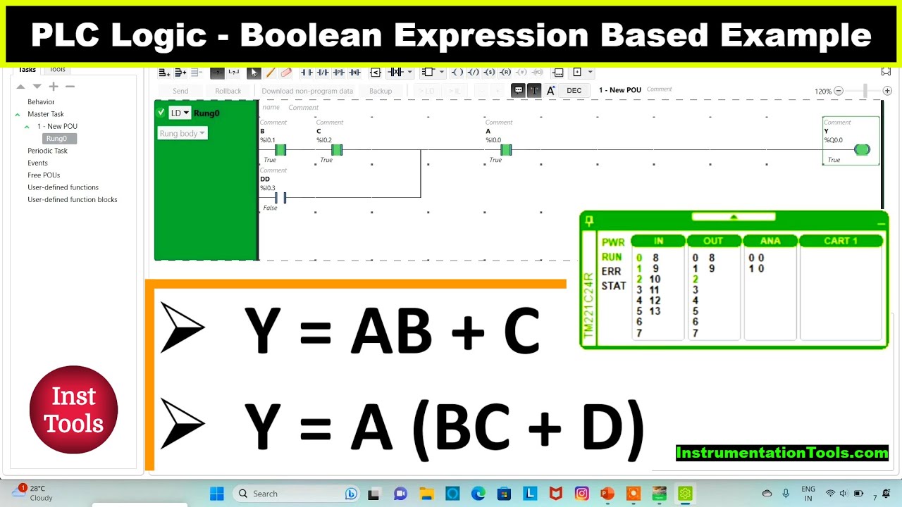
Convert the below boolean expression into equivalent ladder logic.
Y = AB+C
Learn the PLC Example with the Video
Try the video tutorial to learn the PLC example from the start.
Inputs
Digital Inputs:
The required inputs is listed here:
A: I0.0
B: I0.1
C: I0.2
Outputs
Digital Outputs:
The required outputs is listed here:
Y: Q0.0
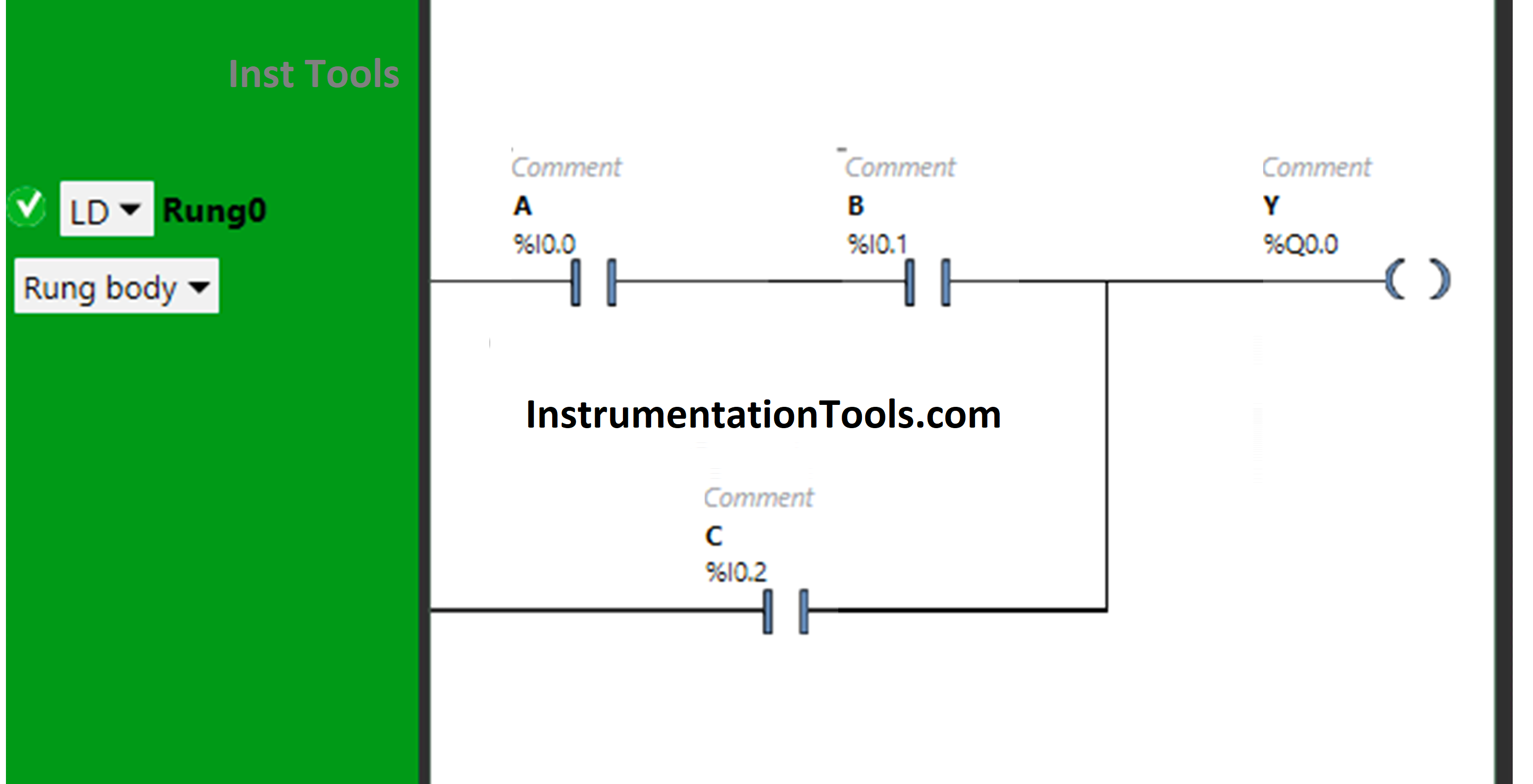
Ladder Logic for Boolean Functions
Program Explained
- Here we used EcoStruxure Machine Expert Basic v1.2 software for programming.
- In the above program, Normally Open Contacts are used for inputs A, B, and C.
- Input A and Input B are connected in series, thus implementing AND Logic Gate.
- For Y (Q0.0) to be ON, either both Input A and Input B should be ON or only Input C should be ON.
- When Input A and B are turned ON, Y (Q0.0) will turn ON because the signal will pass through Input A and Input B as these are Normally Open Contacts.
- Input C is connected in parallel to the output of AB, thus implementing OR Logic Gate.
- The signal will flow through Input C when it is turned ON and pass the signal to turn ON Y(Q0.0).
Simulation Result
Now test the ladder logic and simulate the inputs.
When both Input A and Input B are ON
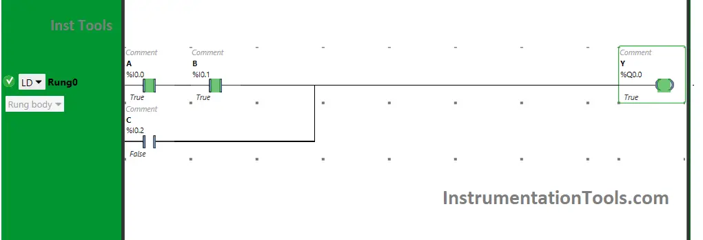
When both Input A and Input B are turned ON, Y (Q0.0) will turn ON. If one of these Inputs is turned OFF, Y (Q0.0) will turn OFF as these are in series implementing AND Logic Gate.
The inputs are used as Normally Open contacts and when in true state, the signal will pass through these inputs and the output will turn ON.
When Input C is ON
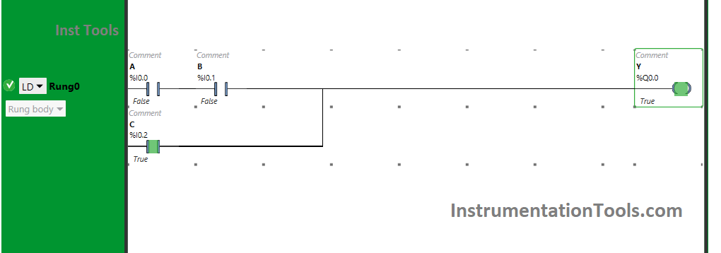
The output Y (Q0.0) will turn ON when Input C is turned ON because the signal will flow through Input C.
The input C is taken as Normally open contact as is connected in parallel. Therefore, turning ON this input only will also turn On the output Y (Q0.0).
If you liked this article, please subscribe to our YouTube Channel for PLC and SCADA video tutorials.
You can also follow us on Facebook and Twitter to receive daily updates.
Read Next:
- Latching and Unlatching in PLC Program
- Memory Bits and Set Coils in Ladder Logic
- PLC with 2 Toggle Switches and 4 Motors
- Rockwell CompactLogix and ControlLogix
- PLC Project Examples EcoStruxure Machine