Inst ToolsInst ToolsInst Tools
  • Courses
  • Automation
    • PLC
    • Control System
    • Safety System
    • Communication
    • Fire & Gas System
  • Instrumentation
    • Design
    • Pressure
    • Temperature
    • Flow
    • Level
    • Vibration
    • Analyzer
    • Control Valve
    • Switch
    • Calibration
    • Erection & Commissioning
  • Interview
    • Instrumentation
    • Electrical
    • Electronics
    • Practical
  • Q&A
    • Instrumentation
    • Control System
    • Electrical
    • Electronics
    • Analog Electronics
    • Digital Electronics
    • Power Electronics
    • Microprocessor
  • Request
Search
  • Books
  • Software
  • Projects
  • Process
  • Tools
  • Basics
  • Formula
  • Power Plant
  • Root Cause Analysis
  • Electrical Basics
  • Animation
  • Standards
  • 4-20 mA Course
  • Siemens PLC Course
Reading: Examples of PLC Programming using Boolean Functions
Share
Font ResizerAa
Inst ToolsInst Tools
Font ResizerAa
  • Courses
  • Design
  • PLC
  • Interview
  • Control System
Search
  • Courses
  • Automation
    • PLC
    • Control System
    • Safety System
    • Communication
    • Fire & Gas System
  • Instrumentation
    • Design
    • Pressure
    • Temperature
    • Flow
    • Level
    • Vibration
    • Analyzer
    • Control Valve
    • Switch
    • Calibration
    • Erection & Commissioning
  • Interview
    • Instrumentation
    • Electrical
    • Electronics
    • Practical
  • Q&A
    • Instrumentation
    • Control System
    • Electrical
    • Electronics
    • Analog Electronics
    • Digital Electronics
    • Power Electronics
    • Microprocessor
  • Request
Follow US
All rights reserved. Reproduction in whole or in part without written permission is prohibited.
Inst Tools > Blog > PLC Tutorials > Examples of PLC Programming using Boolean Functions

Examples of PLC Programming using Boolean Functions

Learn the examples of PLC programming using Boolean functions and implement the equivalent ladder logic.

Last updated: March 25, 2024 2:35 pm
Editorial Staff
PLC Tutorials
No Comments
Share
3 Min Read
SHARE

Learn the examples of PLC programming using Boolean functions and implement the equivalent ladder logic.

Contents
Examples of PLC ProgrammingLearn the PLC Example with the VideoInputsOutputsLadder Logic for Boolean FunctionsProgram ExplainedSimulation Result

Disclaimer: The following logic diagram example is intended for educational purposes, targeting students and engineering graduates to understand PLC basics.

Examples of PLC Programming

Problem Statement

Design a PLC ladder logic for the following Boolean Expression.

We are using toggle Inputs to control the output.

Convert the below boolean expression into equivalent ladder logic.

Y = AB+C

Learn the PLC Example with the Video

Try the video tutorial to learn the PLC example from the start.

PLC Logic - Boolean Expression Based Example

Inputs

Digital Inputs:

The required inputs is listed here:

A: I0.0

B: I0.1

C: I0.2

Outputs

Digital Outputs:

The required outputs is listed here:

Y: Q0.0

Ladder Logic for Boolean Functions
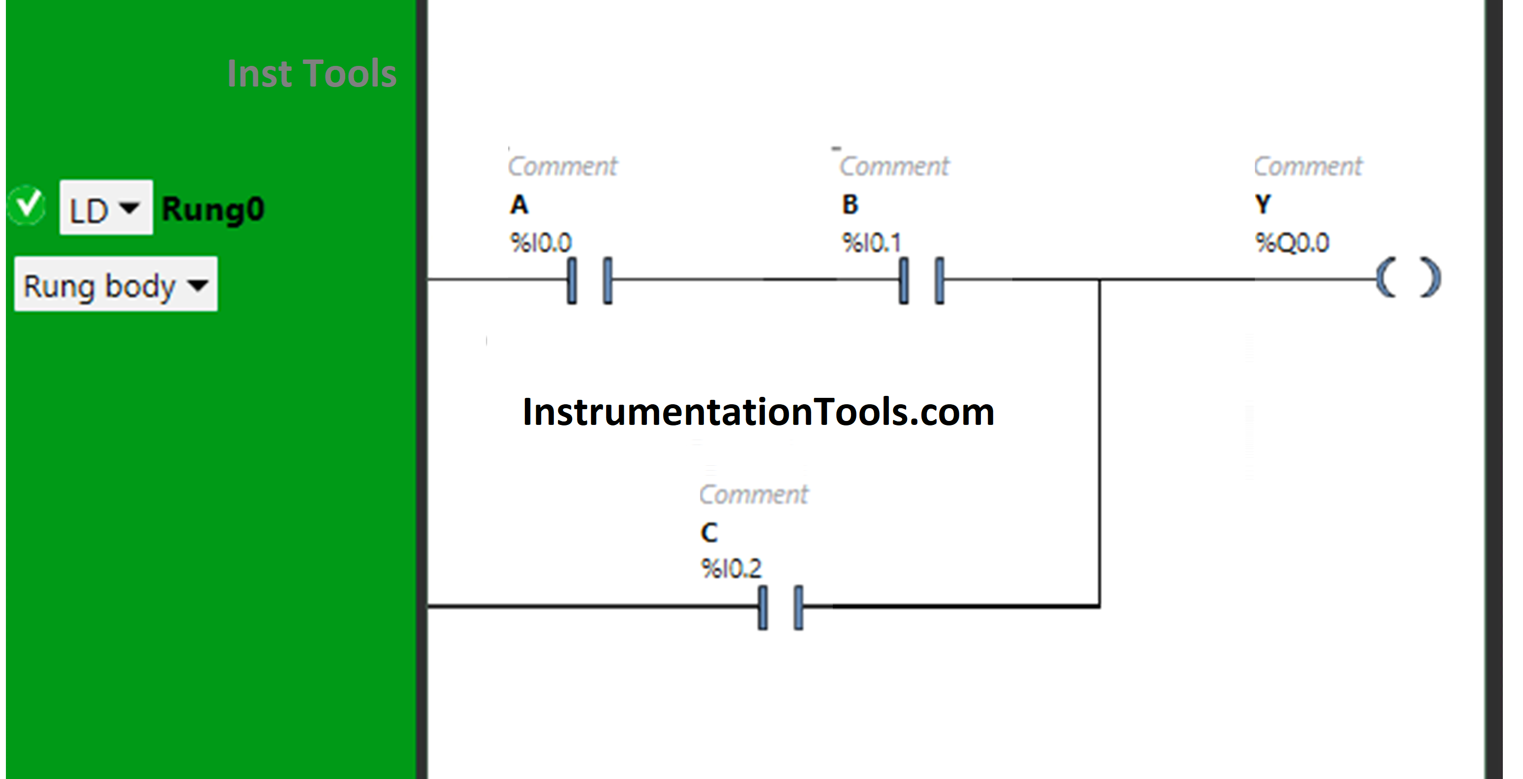
Examples of PLC Programming using Boolean Functions

Program Explained

  • Here we used EcoStruxure Machine Expert Basic v1.2 software for programming.
  • In the above program, Normally Open Contacts are used for inputs A, B, and C.
  • Input A and Input B are connected in series, thus implementing AND Logic Gate.
  • For Y (Q0.0) to be ON, either both Input A and Input B should be ON or only Input C should be ON.
  • When Input A and B are turned ON, Y (Q0.0) will turn ON because the signal will pass through Input A and Input B as these are Normally Open Contacts.
  • Input C is connected in parallel to the output of AB, thus implementing OR Logic Gate.
  • The signal will flow through Input C when it is turned ON and pass the signal to turn ON Y(Q0.0).

Simulation Result

Now test the ladder logic and simulate the inputs.

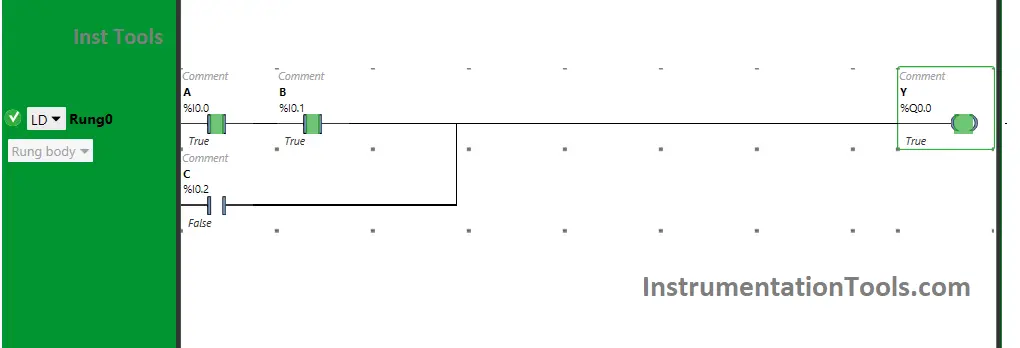
When both Input A and Input B are ON
PLC ladder logic for the Boolean Expression

When both Input A and Input B are turned ON, Y (Q0.0) will turn ON. If one of these Inputs is turned OFF, Y (Q0.0) will turn OFF as these are in series implementing AND Logic Gate.

The inputs are used as Normally Open contacts and when in true state, the signal will pass through these inputs and the output will turn ON.

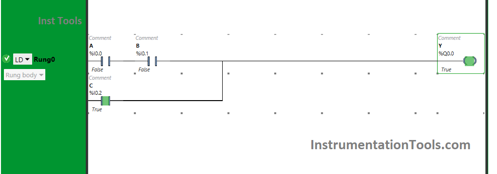
When Input C is ON
implement the equivalent ladder logic

The output Y (Q0.0) will turn ON when Input C is turned ON because the signal will flow through Input C.

The input C is taken as Normally open contact as is connected in parallel. Therefore, turning ON this input only will also turn On the output Y (Q0.0).

If you liked this article, please subscribe to our YouTube Channel for PLC and SCADA video tutorials.

You can also follow us on Facebook and Twitter to receive daily updates.

Read Next:

  • Latching and Unlatching in PLC Program
  • Memory Bits and Set Coils in Ladder Logic
  • PLC with 2 Toggle Switches and 4 Motors
  • Rockwell CompactLogix and ControlLogix
  • PLC Project Examples EcoStruxure Machine
Don't Miss Our Updates
Be the first to get exclusive content straight to your email.
We promise not to spam you. You can unsubscribe at any time.
Invalid email address
You've successfully subscribed !

Continue Reading

FactoryTalk View Studio – Import and Export Tutorial
PLC Analog Input Conversion Formula
Connect to the Siemens S7 PLC
Traffic Light Control using PLC Ladder Logic
PLC Program for Two Way Switch Logic
Omron PLC Logic for Washing Machine Automation
Share This Article
Facebook Whatsapp Whatsapp LinkedIn Copy Link
Share
Leave a Comment

Leave a Reply Cancel reply

Your email address will not be published. Required fields are marked *

Stay Connected

128.3kFollowersLike
69.1kFollowersFollow
210kSubscribersSubscribe
38kFollowersFollow

Categories

Explore More

Industrial Automation and Control Systems (IACS)
Siemens S7 300 and STEP 7 PLC program using SIMATIC Software
How to Upload Siemens PLC Programs?
How to Create Faceplate in FactoryTalk View Studio?
PID Controllers in Closed Loop Control Systems – PLC Basics
Communication between Wincc and Tia Portal
Contacts and Coils in PLC Ladder Logic
Programmable Logic Controller Maintenance Check Points

Keep Learning

Introduction to PLC

Introduction to PLC – Advantages of PLC

Classification of Fuses

Step-by-Step Guide to Choose Right Fuse for a Panel

Best Practices of PLC Wiring

Best Practices of PLC Wiring – Programmable Logic Controller

Difference Between Wifi and Industrial Wireless

Difference Between Wifi and Industrial Wireless

SCADA Run

PLC Based Industrial Conveyor Ladder Logic

OMRON PLC Math Instructions

OMRON PLC Math Instructions: +(400), -(410), *(420), /(430)

Automatic Lamp Control in Storage Facility

PLC Program for Automatic Lamp Control in Storage Facility

FIFO and LIFO Sequences in PLC

What are FIFO and LIFO Sequences in PLC?

Learn More

Working of Stepper Motor

Types of Stepper Motors

Control Valve in Nutshell - Valve Design and Selection Factors

Control Valve in Nutshell – Valve Design and Selection Factors

Solenoid Valve Failure in Plant Start-Up

Solenoid Valve Failure in Plant Start-Up: Identifying the Root Cause

PLC Questions & Answers

Programmable Logic Controller Questions and Answers

Essential Safety Tips for Glass Workers

Essential Safety Tips for Glass Workers

Reformer Fan Bearing Change Times cut by 90%

Reformer Fan Bearing Change Times cut by 90%

Liquefied Petroleum Gas (LPG)

Properties of Liquefied Petroleum Gas (LPG)

Resistor Y and Delta Network Calculation

Y and Delta Resistor Network Calculations

Menu

  • About
  • Privacy Policy
  • Copyright

Quick Links

  • Learn PLC
  • Helping Hand
  • Part Time Job

YouTube Subscribe

Follow US
All rights reserved. Reproduction in whole or in part without written permission is prohibited.
Welcome Back!

Sign in to your account

Username or Email Address
Password

Lost your password?