Plant facilities rely on dependable electrical distribution systems to provide power to key vital equipment. Knowledge of the basic electrical power distribution system and its components will help the operator understand the importance of electrical power distribution systems.
Single Line Diagram
A single, or one-line diagram of a distribution system is a simple and easy-to-read diagram showing power supplies, loads, and major components in the distribution system (Figure 1).
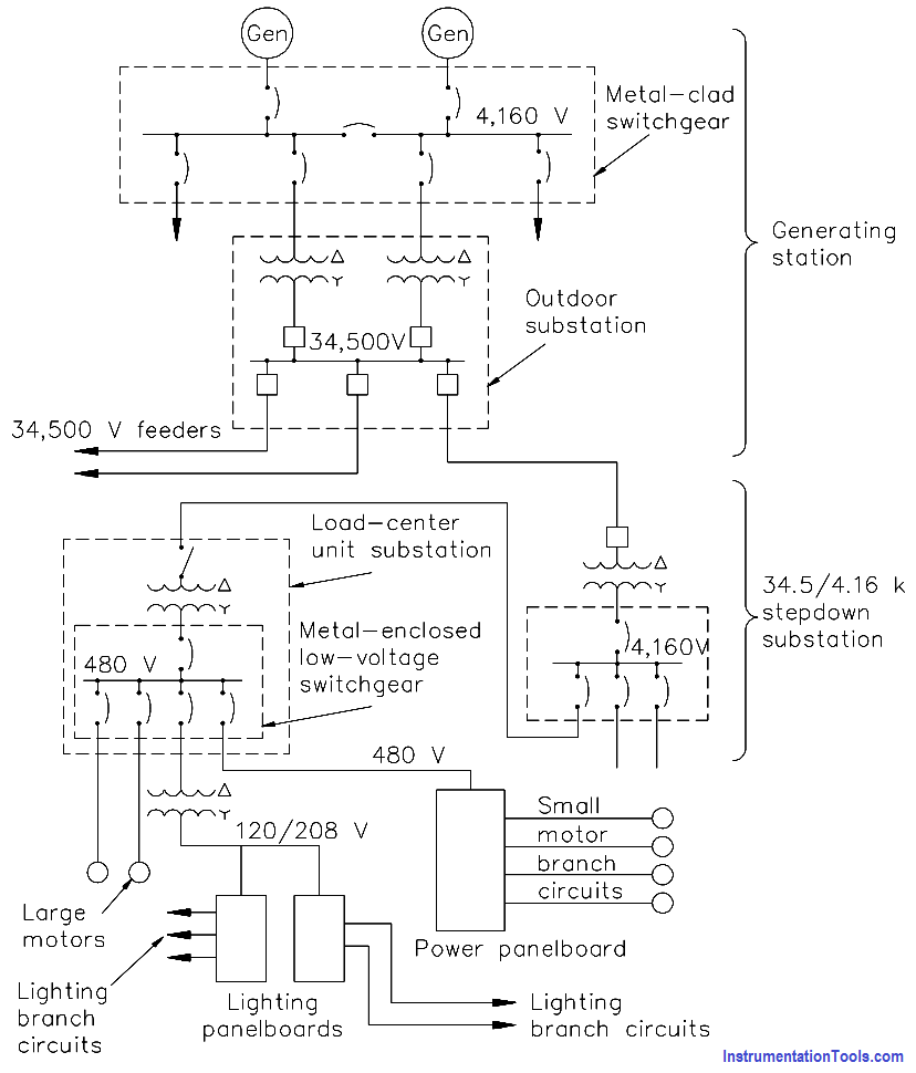
Figure : One-Line Distribution Diagram
Commercial or Utility Power
Commercial or utility power is electrical power that is provided by commercial generating systems to the facility.
Diesel
Power Diesel power is power generated by a diesel-driven generator. Diesel-driven generators are the most economical and practical source of “standby power.”
Failure-Free Power
Failure-free power is accomplished by providing vital equipment with automatic switching between two or more power supplies so that interruption of power is minimized.
Neutral Grounding
Neutral grounding in electrical distribution systems helps prevent accidents to personnel and damage to property caused by: fire in case of lightning; a breakdown between primary and secondary windings of transformers; or accidental contact of high-voltage wires and low- voltage wires.
If some point on the circuit is grounded (in this case neutral ground), lightning striking the wires will be conducted into the ground, and breakdown between the primary and secondary windings of a transformer will cause the primary transformer fuses to blow. Another advantage of neutral grounding is that it reduces the amount of insulation required for high-voltage transmission lines.
Voltage Class
Voltage in distribution systems is classified into three groups: high voltage, intermediate voltage, and low voltage. High voltage is voltage that is above 15,000 volts, intermediate voltage is voltage between 15,000 volts and 600 volts, and low voltage is voltage at 600 volts or less.
Protective Relays
Protective relays are designed to cause the prompt removal of any part of a power system that might cause damage or interfere with the effective and continuous operation of the rest of the system. Protective relays are aided in this task by circuit breakers that are capable of disconnecting faulty components or subsystems.
Protective relays can be used for types of protection other than short circuit or over-current. The relays can be designed to protect generating equipment and electrical circuits from any undesirable condition, such as under-voltage, under-frequency, or interlocking system lineups.
There are only two operating principles for protective relays:
- Electromagnetic attraction and
- Electromagnetic induction.
Electromagnetic attraction relays operate by a plunger being drawn up into a solenoid or an armature that is attracted to the poles of an electromagnet. This type of relay can be actuated by either DC or AC systems. Electromagnetic induction relays operate on the induction motor principle whereby torque is developed by induction in a rotor. This type of relay can be used only in AC circuits.
Overlapping Protective Zones
A separate zone of protection is provided around each system element (Below Figure). Any failure that may occur within a given zone will cause the tripping or opening of all circuit breakers within that zone.
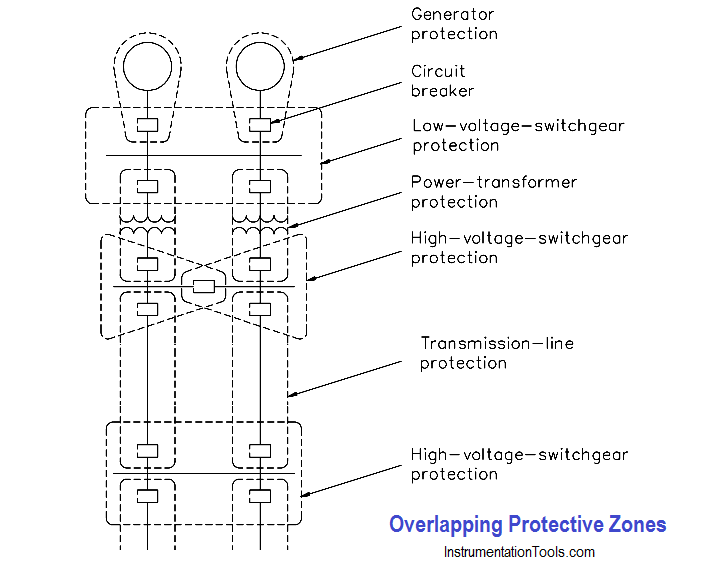
Figure : Protective Relaying Zones
For failures that occur within a region where two protective zones overlap, more breakers will be tripped than are necessary to disconnect the faulty component; however, if there were no overlap of protective zones, a fault in a region between the two zones would result in no protective action at all. Therefore, it is desirable for protective zone overlap to ensure the maximum system protection.
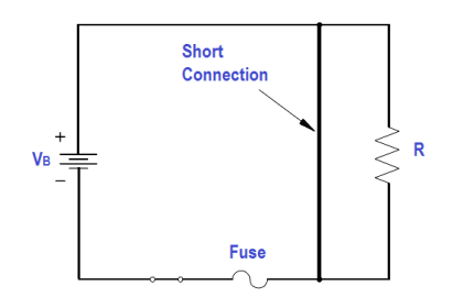
Fuses
A fuse is a device that protects a circuit from an over-current condition only. It has a fusible link directly heated and destroyed by the current passing through it. A fuse contains a current-carrying element sized so that the heat generated by the flow of normal current through it does not cause it to melt the element; however, when an over-current or short-circuit current flows through the fuse, the fusible link will melt and open the circuit. There are several types of fuses in use (below Figure).
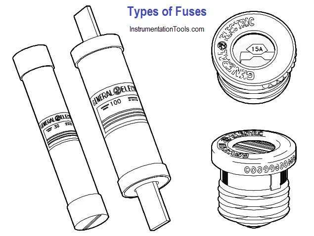
Figure : Types of Fuses
The plug fuse is a fuse that consists of a zinc or alloy strip, a fusible element enclosed in porcelain or pyrex housing, and a screw base. This type of fuse is normally used on circuits rated at 125 V or less to ground and has a maximum continuous current-carrying capacity of 30 amps.
The cartridge fuse is constructed with a zinc or alloy fusible element enclosed in a cylindrical fiber tube with the element ends attached to a metallic contact piece at the ends of the tube. This type of fuse is normally used on circuits rated at either 250 volts or 600 volts and has a maximum continuous current-carrying capacity of 600 amps.