Inst ToolsInst ToolsInst Tools
  • Courses
  • Automation
    • PLC
    • Control System
    • Safety System
    • Communication
    • Fire & Gas System
  • Instrumentation
    • Design
    • Pressure
    • Temperature
    • Flow
    • Level
    • Vibration
    • Analyzer
    • Control Valve
    • Switch
    • Calibration
    • Erection & Commissioning
  • Interview
    • Instrumentation
    • Electrical
    • Electronics
    • Practical
  • Q&A
    • Instrumentation
    • Control System
    • Electrical
    • Electronics
    • Analog Electronics
    • Digital Electronics
    • Power Electronics
    • Microprocessor
  • Request
Search
  • Books
  • Software
  • Projects
  • Process
  • Tools
  • Basics
  • Formula
  • Power Plant
  • Root Cause Analysis
  • Electrical Basics
  • Animation
  • Standards
  • 4-20 mA Course
  • Siemens PLC Course
Reading: Electric Stress Control in Cables, Joints, and Terminations
Share
Notification Show More
Font ResizerAa
Inst ToolsInst Tools
Font ResizerAa
  • Courses
  • Design
  • PLC
  • Interview
  • Control System
Search
  • Courses
  • Automation
    • PLC
    • Control System
    • Safety System
    • Communication
    • Fire & Gas System
  • Instrumentation
    • Design
    • Pressure
    • Temperature
    • Flow
    • Level
    • Vibration
    • Analyzer
    • Control Valve
    • Switch
    • Calibration
    • Erection & Commissioning
  • Interview
    • Instrumentation
    • Electrical
    • Electronics
    • Practical
  • Q&A
    • Instrumentation
    • Control System
    • Electrical
    • Electronics
    • Analog Electronics
    • Digital Electronics
    • Power Electronics
    • Microprocessor
  • Request
Follow US
All rights reserved. Reproduction in whole or in part without written permission is prohibited.
Inst Tools > Blog > Electrical Basics > Electric Stress Control in Cables, Joints, and Terminations

Electric Stress Control in Cables, Joints, and Terminations

Learn how to control electric stress in cables to prevent damage to insulating material and ensure the integrity of your wires.

Last updated: September 18, 2024 7:39 am
Viral Nagda
Electrical Basics
No Comments
Share
6 Min Read
SHARE

When you are using an electric cable, it is bound with a common issue called electric stress. If this issue is not solved, then the cable will either lose its insulating material or will burn the wire itself.

Contents
What is electric stress?Reasons for electric stressMethods of electric stress controlGeometric stress controlCapacitive stress controlGood TerminationsExtend the lug or the terminator end

Many engineers accidentally ignore this concept and due to this, after a period of time, the wire starts to lose its integrity. In this post, we will see the concept of electric stress in cables, joints, and terminations, and will see how to control it.

What is electric stress?

When you are connecting a wire in a joint or termination, you need to open some conductor part of the wire and join with the terminators, failure of which will not cause current to flow.

When the wire cover is opened, it means that the area is no longer insulated. Due to loss of insulation or less amount of insulation in that area, the electric voltage from the conductor will now start to flow from that area.

This means that the electric field is now flowing outside the conductor core of the wire into non-insulated areas. If the field starts to distribute in such a scattered way, undesired areas of the wires will have conduction.

This can result in the heating of the cable, ultimately leading to failure. Also, if a person accidentally touches that area thinking it is non-conductive, then it may lead to electric shock. This is called electric stress.

An electric stress tests the dielectric strength of insulating materials of the wire, and its performance when a certain voltage is applied to them. It matters mostly in high voltage applications like power transmission and generation. It is calculated by considering applied electric fields as well as voltage. If the stress is high, then the dielectric material will fail and thus, the cable will fail.
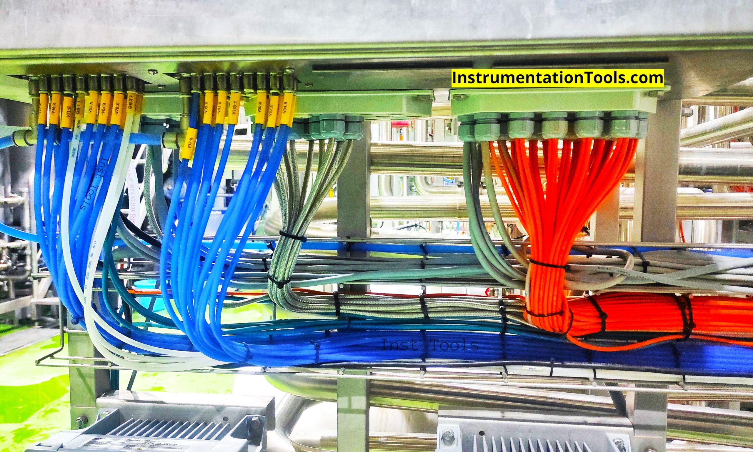
Electric Stress Control in Cables, Joints and Terminations

Now, as discussed, cables and joints play a very important role in controlling stress. This is because they are responsible for terminating the cables and thus removing any possibility of an open connection or end. If it is not done properly by leaving out any edge or space, then it invites stress unnecessarily.

Reasons for electric stress

The the main reasons for the electric stress are listed below.

  1. Improper termination results in some open edges or space around the conducting core.
  2. Improper earthing can result in leakage current and electromagnetic noise, affecting the dielectric strength of the insulating material.
  3. Exposure to moisture or accidental spillage of water on the cable ends.
  4. Poor quality cable.
  5. Improper lugs applied to cable joints and ends.

Methods of electric stress control

The popular stress control methods are listed here.

  1. Geometric stress control
  2. Capacitive stress control
  3. Good Terminations
  4. Extend the lug or the terminator end

Geometric stress control

The first method is called geometric stress control. In this, an extra layer of insulator is added over the already-insulated surface of the cable. As the cable approaches its end, this extra layer of insulation starts to increase. You can think of it as a ramp.

At the extreme end of the cable, the insulation material will be the highest. In short, the areas with a high ratio of electric stress receive an extra layer of insulation.

Capacitive stress control

The second method is called capacitive stress control. Instead of applying an extra layer of insulation, the same area of insulation is added, but with a material of high dielectric constant.

This reduces the surface tension area of the electric field to a great extent, as the capacitance is increased due to the high dielectric constant. It is seen practically that out of the two – geometric and capacitive, the capacitive works best in high voltage applications.

Good Terminations

The third method involves the use of a good termination. When choosing the best termination for your cable, see the following factors –

  • resistance to high flashover voltage
  • ease in installation
  • resistance to tracking and UV radiation
  • resistance to pollution, moisture, dust, and fog

If termination only is solved at its base end, then the need for implementing other methods reduces to a great extent.

Extend the lug or the terminator end

The next method is to extend the lug or the terminator end beyond its limit. This means, suppose a lug is installed to cover the open conductor core of wire to 10 mm, then use a lug which can cover 20 mm.

A more practical example is using a stress cone. It is a material used best for electric stress control as it extends finely beyond the termination end.

In this way, we saw the concept of electric stress control in cables, joints, and terminations.

Read Next:

  • MCB vs Fuse Questions and Answers
  • Electrical Engineering Documents Quiz
  • Difference Between HV and LV Cables
  • Types of Cables in Industrial Automation
  • Flame Resistant and Retardant Cables
Don't Miss Our Updates
Be the first to get exclusive content straight to your email.
We promise not to spam you. You can unsubscribe at any time.
Invalid email address
You've successfully subscribed !

Continue Reading

Advantages of Valve Regulated Lead Acid (VRLA) Batteries
Difference between Signal Cables and Control Cables
Why CT Secondary Should Never Be Kept Open?
What is a Substation? Purpose of an Electrical Substation
What is a Lightning Arrester? How does it work?
Why Are Neutral and Earth Separated?
Share This Article
Facebook Whatsapp Whatsapp LinkedIn Copy Link
Share
Leave a Comment

Leave a Reply Cancel reply

Your email address will not be published. Required fields are marked *

Stay Connected

128.3kFollowersLike
69.1kFollowersFollow
210kSubscribersSubscribe
38kFollowersFollow

Categories

Explore More

Electrical Contactor Interlocking Circuit Explained
Difference Between HV and LV Cables
What is an Inductor? – Types of Inductors
Assembling an Electrical Conduit Seal
Difference Between NEMA and IEC Motors?
Electric Motor Winding Temperature Sensors
How does an Electric Motor Operate? – AC Motor Fundamentals
How to Check the Continuity of Protective Conductors?

Keep Learning

Types of Switches

Electrical Switches Principle & Types

Difference Between Emergency STOP and Emergency Power OFF

Difference Between Emergency STOP and Emergency Power OFF

Why is Motor Control Required in Control Systems

Why is Motor Control Required in Control Systems?

Types of Tripping Protection in MCCB

Types of Tripping Protection in MCCB

LBB protection relay

What is the LBB Protection Relay? (Local Breaker Backup)

What is a Core Type Transformer

Difference Between Core and Shell Transformers

hand-crank megger photo

What is Megger Test?

Capacitor Bank

What is a Capacitor Bank?

Learn More

Safety interlock for motor starters in Siemens PLC

Motor Starter Logic using Siemens PLC Tia Portal

Reverse Voltage Characteristics of Photo diode

Characteristics of Photo diode

DC Circuit

Main differences between Sinking and Sourcing Circuits

How to do Force in GE PLC Proficy Machine Edition?

Concept of DCS in Industrial Automation

Concept of DCS in Industrial Automation

Needle Valve Schematic

How Needle Valve Works ?

Analog Electronics Projects

Analog Electronic Projects for Final Year Engineering Students

Basics of Trips, Interlocks, Permissives & Sequences

Basics of Trips, Interlocks, Permissives & Sequences

Menu

  • About
  • Privacy Policy
  • Copyright

Quick Links

  • Learn PLC
  • Helping Hand
  • Part Time Job

YouTube Subscribe

Follow US
All rights reserved. Reproduction in whole or in part without written permission is prohibited.
Welcome Back!

Sign in to your account

Username or Email Address
Password

Lost your password?