To study the working of Up Counter PLC program in Allen Bradley Programmable Logic Controller (PLC).
Down Counter
 Instruction")
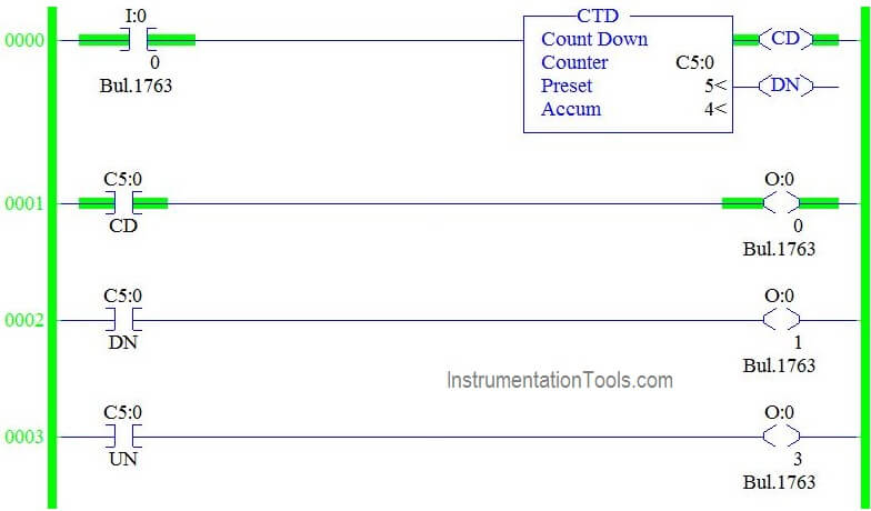
In the above picture, there are totally three parameter,
COUNTER: C4:0 – Counter File name (TimerC5:0, C5:1,C5:2…)
PRESET – PRE : Limit value of COUNT-Up to how much it should count
ACCUMULATOR – ACC : Running Value of counter when condition turn ON.

From the data file,along with preset and accumulator, we have few more bits,
CD: Countdown Bit-whenever the counter is enable makes this bit to go ON.
DN: Done Bit-When accumulator value equals preset value, done bit turns to ON.
UA: Counter Underflow – When accumulator value reached the limit value (-32767),it rolls back to +32767 for the upcoming counter operation, underflow bit turns ON, in this condition.
Notes:
UA – Update Accumulator Value-Only used when high speed counters are used in the program.
CU & OV – Used for Up Counter Function.
Down Counter Description Using PLC Program
I:0/0 is used to give input to counter and Preset value and accumulator value set to 5.
Counter Count Down Bit (C5:0/DN)
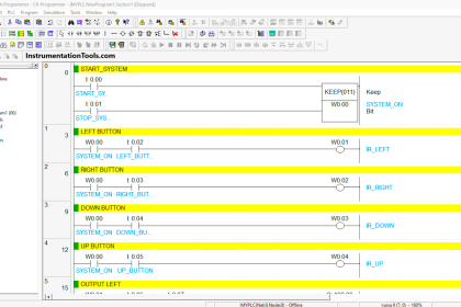
In the below Ladder logic,
Rung 0000
Having condition input I:0/0 which gives input to counter to perform counter down function.
Rung 0001
Having Counter CU Bit which enable only when counter is in function or when input to the counter turns ON and accumulator value counted down.
Rung 0002
Counter done bit turns on when accumulator value equals preset value.

Counter Count Down Bit (C5:0/CD):
In the below Ladder logic,
Rung 0000
Having condition input I:0/0 which gives input to counter to perform counter function.
Rung 0001
Having Counter CU Bit which enable only when counter is in function or when input to the counter turns ON and accumulator value counted down.
In the below Ladder logic,
Rung 0000
Having condition input I:0/0 which gives input to counter to perform counter function. Accumulator value goes to negative if I:0/0 goes ON for 6th time in the below case,

Counter Under Flow Bit (C5:0/UN):
In the Below Ladder Logic,
Counter accumulator value under flows when accumulator value reaches -32767 in Allen Bradley PLC Programming.

In the below ladder Logic,
When we turn ON the I:0/0 ,accumulator value rolls back to 32768 and start counting down from 32767 to -32767.Counter underflow bit turns ON when this condition happen (Rung 003).

Conclusion:
We can use this explanation to understand the working of Down Counter function in Allen Bradley Programmable Logic Controller (PLC).
If you liked this article, then please subscribe to our YouTube Channel for PLC and SCADA video tutorials.
You can also follow us on Facebook and Twitter to receive daily updates.
Read Next:


Hello Hema,
Please, is there a way to hinder the countdown of the counter from reaching the negative count values without using a limits or comparison instructions?