Inst ToolsInst ToolsInst Tools
  • Courses
  • Videos
  • Q & A
    • Interview
      • Instrumentation
      • Electronics
      • Electrical
      • Practical Questions
    • MCQ
      • Instrumentation MCQ
      • Electrical MCQ
      • Electronics MCQ
      • Control Systems MCQ
      • Analog Electronics MCQ
      • Digital Electronics MCQ
      • Power Electronics MCQ
      • Microprocessor MCQ
      • Multiple Choice Questions
  • EE
    • Electronics
      • Electronics Q & A
      • Electronic Basics
      • Electronic Devices & Circuits
      • Electronics Animation
      • Digital Electronics
    • Electrical
      • Electrical Basics
      • Electrical Q & A
      • Power Electronics
      • Electrical Machines
      • Electrical Animation
      • Power Systems
      • Switchgear & Protection
      • Transmission & Distribution
  • Measure
    • Control Valves
    • Calibration
    • Temperature
    • Pressure
    • Flow
    • Level
    • Analyzers
    • Switches
    • Vibration
    • Solenoid Valve
  • Control
    • PLC Tutorials
    • Control Systems
    • Safety Instrumented System (SIS)
    • Communication
    • Fire & Gas System
  • More
    • Design
    • Tools
    • Animation
    • Basics
    • Formulas
    • Standards
    • TextBooks
    • Common
    • Software
    • Excel Tools
    • Erection & Commissioning
    • Process Fundamentals
    • Videos
    • Books
Search
All rights reserved. Reproduction in whole or in part without written permission is prohibited.
Reading: Double Block and Bleed Valves Opening or Closing Sequence
Share
Notification Show More
Font ResizerAa
Inst ToolsInst Tools
Font ResizerAa
  • Courses
  • PLC Tutorials
  • Control Systems
Search
  • Courses
  • Videos
  • Q & A
    • Interview
    • MCQ
  • EE
    • Electronics
    • Electrical
  • Measure
    • Control Valves
    • Calibration
    • Temperature
    • Pressure
    • Flow
    • Level
    • Analyzers
    • Switches
    • Vibration
    • Solenoid Valve
  • Control
    • PLC Tutorials
    • Control Systems
    • Safety Instrumented System (SIS)
    • Communication
    • Fire & Gas System
  • More
    • Design
    • Tools
    • Animation
    • Basics
    • Formulas
    • Standards
    • TextBooks
    • Common
    • Software
    • Excel Tools
    • Erection & Commissioning
    • Process Fundamentals
    • Videos
    • Books
Follow US
All rights reserved. Reproduction in whole or in part without written permission is prohibited.
Inst Tools > Blog > Practical Questions > Double Block and Bleed Valves Opening or Closing Sequence

Double Block and Bleed Valves Opening or Closing Sequence

Last updated: September 11, 2020 10:14 am
Editorial Staff
Practical Questions Pressure Measurement
No Comments
Share
2 Min Read
SHARE

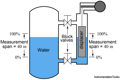
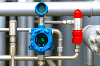
On processes where the fluid in question is especially dangerous, “double block and bleed” valve manifolds are often used to isolate pressure measuring instruments (like pressure gauge, pressure transmitters, etc) from the process.

Contents
Double Block and Bleed ValvesAnswer:Removing the gauge from service:Placing the gauge back into service:Read Next:

Double Block and Bleed Valves

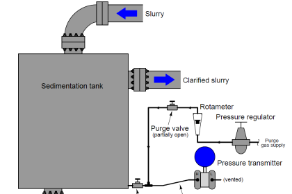
Consider this example:

Double Block and Bleed Valves Opening or Closing Sequence

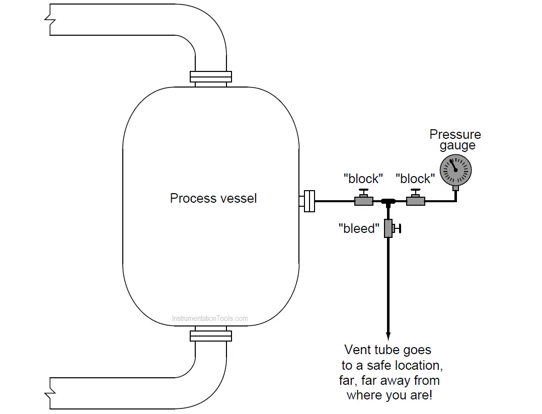
Describe the proper procedure for block and bleed valve opening/closing when removing and replacing an instrument connected to a process through such a manifold.

Answer:

Removing the gauge from service:

  • Close the “block” valve closest to the process.
  • Open the “bleed” valve. Monitor the instrument’s pressure indication, to make sure it is changing to register atmospheric pressure. This tells you that the “bleeding” is successful.
  • Close the “block” valve closest to the instrument.
  • Close the “bleed” valve.
  • Place lock-out tags on all three valve handles to notify operators and technicians of the instrument’s removal and pending return.
  • Remove the gauge from the piping or tubing.

Assuming the process fluid is especially dangerous, there may be some sort of recommended decontamination process for the instrument prior to you connecting it to calibration equipment in the shop. As always, be aware of any special safety considerations on any process you are working around.

Placing the gauge back into service:

  • Remove the lock-out tags on all valve handles.
  • Open the “bleed” valve (to relieve any pressure that may have built up between the two closed block valves from a leak in the first block valve).
  • Re-attach the gauge to the piping or tubing.
  • Open the “block” valve closest to the instrument.
  • Close the “bleed” valve.
  • Open the “block” valve closest to the process.

Share your answers with us through below comments section.

Read Next:

  • Heat Exchanger DP Transmitter
  • P&ID Guidelines for Valves
  • Single Block and Bleed Valve
  • Pressure Transmitter Vent fitting
  • 5 Way Valve Manifold Operation

Credits: Tony R. Kuphaldt

Don't Miss Our Updates
Be the first to get exclusive content straight to your email.
We promise not to spam you. You can unsubscribe at any time.
Invalid email address
You've successfully subscribed !

Recommended Articles

Interview Questions on Differential Pressure Flow Transmitter
Differential Pressure Sensors Calibration Procedure
Well Manometer Principle
Calculate Hydraulic Pressure of a Process Vessel
U-tube Manometer with equal & unequal limb types
Pressure Gauges : Remote and Chemical Seals
Share This Article
Facebook Whatsapp Whatsapp LinkedIn Copy Link
Share
Leave a Comment

Leave a Reply Cancel reply

Your email address will not be published. Required fields are marked *

Stay Connected

128.3kFollowersLike
69.1kFollowersFollow
208kSubscribersSubscribe
38kFollowersFollow

Categories

Recent Comments

  • William Snyder on Top Non-PLC Certification Courses for Automation Professionals
  • Kamli on Top Free PLC Software
  • Guifty Shimica on Top Non-PLC Certification Courses for Automation Professionals
  • Guifty Shimica on Top Non-PLC Certification Courses for Automation Professionals

Related Articles

Fieldbus Pressure Transmitter Configuration

Foundation Fieldbus Pressure Transmitter Configuration

level control system

Practical Process Control System Questions & Answers – 10

Programmable Logic Controller (PLC) Questions and Answers – 9

Fisher model 546 I to P transducer

Fisher model 546 I/P transducer

liquid flow control loop

Liquid Flow Control Loop Controller Action

Pneumatic Transmitter

Pneumatic Level Transmitter Calibration Table

Absolute Pressure Gauges Principle

Absolute Pressure Gauges Principle

Air Pressure Regulator cut-away diagram

Air Pressure Regulator Questions

More Articles

ON and OFF a Group of Outputs by One Push button PLC Logic

ON and OFF a Group of Outputs by One Push button PLC Logic

Instrumentation Loop Diagram

Loop diagram and System Inspection Lab Exercise

Sample Raw DataSheet for Pressure Calibration

Sample Raw DataSheet for Pressure Calibration

Area Velocity Flow Meter Principle

Area Velocity Flow Meter Principle

HVAC Multiple Choice Questions

HVAC Multiple Choice Questions

peak of a chromatogram

Measuring Gases Concentration in Chromatograph

Types of Engineering Courses

Various Types of Engineering Courses

Create Ladder Diagram from Boolean Logic

Create Ladder Diagram from Boolean Logic

Follow US
All rights reserved. Reproduction in whole or in part without written permission is prohibited.
Welcome Back!

Sign in to your account

Username or Email Address
Password

Lost your password?