By using this site, you agree to the Privacy Policy and Terms of Use.
Accept
Inst ToolsInst ToolsInst Tools
  • Ask
  • Courses
  • Videos
  • Q & A
    • Interview
      • Instrumentation
      • Electronics
      • Electrical
      • Practical Questions
    • MCQ
      • Instrumentation MCQ
      • Electrical MCQ
      • Electronics MCQ
      • Control Systems MCQ
      • Analog Electronics MCQ
      • Digital Electronics MCQ
      • Power Electronics MCQ
      • Microprocessor MCQ
      • Multiple Choice Questions
  • EE
    • Electronics
      • Electronics Q & A
      • Electronic Basics
      • Electronic Devices & Circuits
      • Electronics Animation
      • Digital Electronics
    • Electrical
      • Electrical Basics
      • Electrical Q & A
      • Power Electronics
      • Electrical Machines
      • Electrical Animation
      • Power Systems
      • Switchgear & Protection
      • Transmission & Distribution
  • Measure
    • Control Valves
    • Calibration
    • Temperature
    • Pressure
    • Flow
    • Level
    • Analyzers
    • Switches
    • Vibration
    • Solenoid Valve
  • Control
    • PLC Tutorials
    • Control Systems
    • Safety Instrumented System (SIS)
    • Communication
    • Fire & Gas System
  • More
    • Design
    • Tools
    • Animation
    • Basics
    • Formulas
    • Standards
    • TextBooks
    • Common
    • Software
    • Excel Tools
    • Erection & Commissioning
    • Process Fundamentals
    • Videos
    • Books
Search
© 2022 Foxiz News Network. Ruby Design Company. All Rights Reserved.
Reading: Distributed Temperature Sensors (DTS) in Power Lines
Share
Notification Show More
Font ResizerAa
Inst ToolsInst Tools
Font ResizerAa
  • Ask
  • Courses
  • Videos
  • Q & A
  • EE
  • Measure
  • Control
  • More
Search
  • Ask
  • Courses
  • Videos
  • Q & A
    • Interview
    • MCQ
  • EE
    • Electronics
    • Electrical
  • Measure
    • Control Valves
    • Calibration
    • Temperature
    • Pressure
    • Flow
    • Level
    • Analyzers
    • Switches
    • Vibration
    • Solenoid Valve
  • Control
    • PLC Tutorials
    • Control Systems
    • Safety Instrumented System (SIS)
    • Communication
    • Fire & Gas System
  • More
    • Design
    • Tools
    • Animation
    • Basics
    • Formulas
    • Standards
    • TextBooks
    • Common
    • Software
    • Excel Tools
    • Erection & Commissioning
    • Process Fundamentals
    • Videos
    • Books
Follow US
© 2022 Foxiz News Network. Ruby Design Company. All Rights Reserved.
Inst Tools > Blog > Temperature Measurement > Distributed Temperature Sensors (DTS) in Power Lines
Temperature MeasurementElectrical Basics

Distributed Temperature Sensors (DTS) in Power Lines

Viral Nagda
Last updated: September 28, 2022 4:09 pm
Viral Nagda
Share
5 Min Read
SHARE

In this post, we will understand the theory of distributed temperature sensors, also known as DTS sensors, in power lines.

Contents
Distributed Temperature SensorsApplications of DTS SensorsAdvantages of Distributed Temperature Sensors

The temperature of a power line must be maintained properly, for efficient operation and output. Temperature monitoring also helps in leakage detection and fire detection.

Power lines are laid in kilometres and traditional sensing methods were very hard and cumbersome to detect temperature.

Discrete sensors were used at predefined points; which sometimes caused less efficiency. This was because the areas which were not covered under these sensors went undetected and if any issue occurred in temperature, it could not be traced out.

The uneven temperature in parts of the power line is harmful to operation. So, to monitor the temperature in the whole power line, distributed temperature sensors were developed and it is the most used ones for this application.

DTS is nothing but a sensor system deploying optical fibre throughout the length of the power cable (in kilometres).

Optical fibres here do not work as a data transfer mechanism but work as temperature sensors. This gets a continuous temperature profile of the cable.

The great Indian physicist, Dr C.V. Raman, discovered that when light traverses a transparent material, some of the deflected light changes in wavelength.

This light scattering effect developed DTS sensors. Let us understand it in simpler terms.

Distributed Temperature Sensors

Basically, the DTS system comprises a DTS transmitter-receiver, optical fibre cable and a PC software analyzer. Optical fibre is laid throughout the power cable.

Continuous laser pulses are sent from the transmitter into the fibre optic cable (shown in blue colour). If you see the image below, you can see that light rays emitted from equipment travel in forward direction (shown in green colour).

Light always scatters at every interval with changes in temperature. Due to this scattering, that particular pulse of light travels in the opposite direction (shown in grey colour). The DTS equipment will receive each of these pulses.

Distributed Temperature Sensors

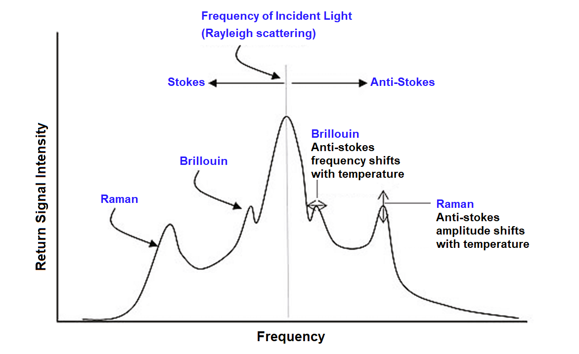
Now, refer to the below image to understand the effect of temperature on light scattered. Stokes means the low frequency of light scattered and anti-stokes means the high frequency of light scattered.

If the temperature is higher, then the amplitude and frequency will increase; and if the temperature is lower, then the amplitude and frequency will decrease.

The centre line shown in grey colour is the typical frequency of a light pulse in the cable. The peaks shown in the figure (Raman and Brillouin) are the temperature peaks of the light signal received.

Typically, every 1 meter in the cable layout will generate scattered light; and so, if the cable length is 10 km, then there would be around 10000 reflected pulses received at regular intervals in the DTS equipment.

That means, you get a very high coverage area for the entire cable length and you will be able to monitor so many temperature points.

DTS sensors

The peak height determines the temperature and the received time of the pulse determines the position of the peak in the cable length. The position is measured by a technique called as Optical Time Domain Reflectometry (OTDR).

Multimode fibre cables can operate till 40 km and single-mode fibre cables can operate till 100 km. Optical fibre is used because according to Raman’s theory, the transparent material is available here in the form of doped quartz glass.

Applications of DTS Sensors

DTS sensors are a very useful tool not just in the electrical system; but also in other sectors like oil and gas, chemical, tunnels, industrial conveyor belts, mines, hazard buildings etc.

In all these applications, optical fibre cable is laid over the media to be checked.

Advantages of Distributed Temperature Sensors

Due to distributed temperature sensors’ high efficiency and reduced complexity, the cost of installation and maintenance also decreases.

But, it is to be considered that due to specific environmental conditions where the cable is laid, it must also be coated with some special protective film.

In this way, we understood the basic working principle of DTS sensors.

Don't Miss Our Updates
Be the first to get exclusive content straight to your email.
We promise not to spam you. You can unsubscribe at any time.
Invalid email address
You've successfully subscribed !
Why Are Charcoal and Salt Added to an Earthing Pit?
Difference Between Flame Resistant and Flame Retardant Cables
How RTD Measuring the Temperature
Basic Electrical Engineering Questions & Answers
Types of Earth Leakage Circuit Breaker
Share This Article
Facebook Whatsapp Whatsapp LinkedIn Copy Link
Share
Leave a Comment Leave a Comment

Leave a Reply Cancel reply

Your email address will not be published. Required fields are marked *

Stay Connected

128.3kFollowersLike
69.1kFollowersFollow
206kSubscribersSubscribe
38kFollowersFollow

Latest

Top Non-PLC Certification Courses for Automation Professionals
Common
Things You Need to Know About DeviceNet
Communication
Why is IEC 60269 Important
Why is IEC 60269 Important? – Electrical Applications
Standards
NAMUR OPEN ARCHITECTURE
What is NAMUR OPEN ARCHITECTURE?
Control Systems

You Might also Like

Residual Current Circuit Breaker (RCCB)
Electrical Basics

Residual Current Circuit Breaker (RCCB)

R Jagan Mohan Rao
R Jagan Mohan Rao
December 24, 2020
Automatic Motor Forward and Reverse Control using Timer
Electrical BasicsPLC Tutorials

Automatic Motor Forward and Reverse Control using Timer

K Mugunthan
K Mugunthan
April 2, 2025
How to Test a Thermocouple with a Multimeter
Temperature Measurement

Testing a Thermocouple With a Multimeter

Editorial Staff
Editorial Staff
March 17, 2016
Thermocouple Temperature Measurements Errors
Erection & CommissioningTemperature Measurement

Thermocouple Temperature Measurement Errors

Editorial Staff
Editorial Staff
June 2, 2016
Semiconductor Fuse
Electrical Basics

What is a Semiconductor Fuse?

Viral Nagda
Viral Nagda
March 17, 2023
Types of Switches
CommonElectrical BasicsPLC Tutorials

Electrical Switches Principle & Types

Editorial Staff
Editorial Staff
December 17, 2016
//

Inst Tools

Sign Up for Our Newsletter

Subscribe to our newsletter to get our newest articles instantly!

[mc4wp_form id=”847″]

Follow US
All Rights Reserved.
Welcome Back!

Sign in to your account

Username or Email Address
Password

Lost your password?