In general, the exchange of signals between electrical systems (MCC) and Distributed Control systems (DCS) is implemented based on a plant control philosophy.
All signals for motor control and monitoring will be exchanged between DCS and MCC is exchanged on the Ethernet platform; it is called iMCC (Intelligent motor control center) to the extent possible or else if it is connected with simple hardware wiring then it is called non-iMCC (simply MCC).
Distributed Control System Interface Philosophy
In manufacturing industries, the following signals are commonly used in order to full fill the process requirement and atomization of the process.
- Stop/Trip Command from DCS (Digital output)
- Start Command from DCS (Digital output)
- Run/Off Indication on DCS (Digital Input)
- Trip Indication on DCS (Digital Input)
- Current/Power Indication on DCS (Analog Input)
- In the case of VFD, Output from DCS for speed set point and input to DCS to monitor the actual speed of the motor (Analog output)
- Auto/manual or Remote/local selection of motor on DCS (Digital Input)
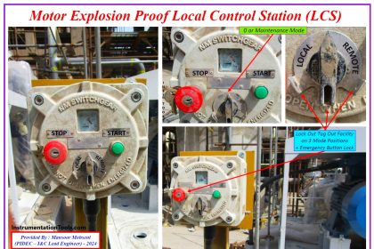
- Emergency stop from field to DCS (Digital Input)
- Auto/manual or remote/local indication of VFD on DCS (Digital Input)
- Ready to start signal on DCS (Digital output)
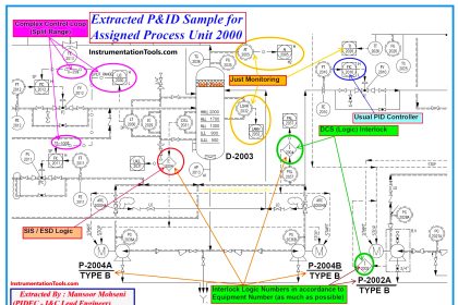
Critical motor interlocks are implemented in the ESD system and non-critical motor interlocks of motors are implemented in DCS as per operation control philosophy.
Motor Control Center Interface Philosophy
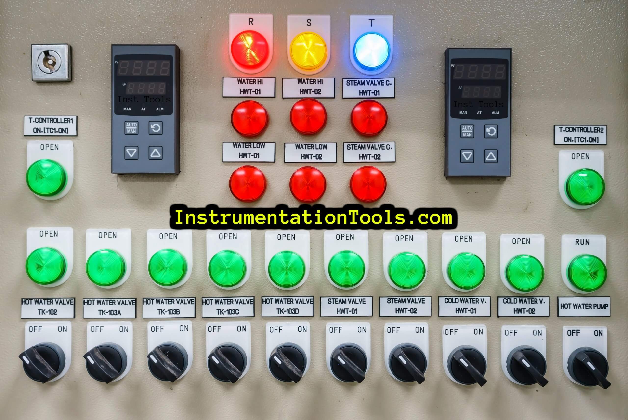
Furthermore, if we use hardwire interface between MCC and DCS/PLC, then all the commands from DCS/PLC should be potential free with the switching of relay contact because generally 230 VAC is used in the control circuit of the motor feeder and indication feedback from MCC to DCS/PLC also remains potential free contact for protection of DCS/PLC cards.
There are analog signals used between VFD and DCS/PLC for the indication of Current (A) and Speed RPM on the DCS workstations and these are analog input signals (AI, 4-20 mA). Also, DCS/PLC sends the motor speed set point signal to VFD as analog output (AO) same as (4-20 mA).
VFD is also connected to DCS/PLC on the Modbus link and all required data is exchanged on this communication channel (optional).
If the motor is related to the critical equipment category as per process and interlock pertaining to the ESD system, then one interlock command signal is used for tripping the motor during abnormal operation this command signal comes from the ESD system.
In most industries, there is an IRP cabinet (Interposing Relay panel) installed in between the DCS/PLC system and Motor Control Center (MCC). This panel is installed in the control room. This is used for the isolation of different voltage signals and the protection of electronic cards mounted in DCS/PLC panels.
Thus, all the above control signals are used for the operation of motors in manufacturing industries, and during commissioning time, all signals are checked individually, and loop tests will be performed for each indication and command signal.
If you liked this article, then please subscribe to our YouTube Channel for Electrical, Electronics, Instrumentation, PLC, and SCADA video tutorials.
You can also follow us on Facebook and Twitter to receive daily updates.
Read Next:
- Gas Metering System
- Faults in PID Control Loop
- Industrial System Checklist
- Power Factor Controller (PFC)
- Building Management System
