Inst ToolsInst ToolsInst Tools
  • Courses
  • Automation
    • PLC
    • Control System
    • Safety System
    • Communication
    • Fire & Gas System
  • Instrumentation
    • Design
    • Pressure
    • Temperature
    • Flow
    • Level
    • Vibration
    • Analyzer
    • Control Valve
    • Switch
    • Calibration
    • Erection & Commissioning
  • Interview
    • Instrumentation
    • Electrical
    • Electronics
    • Practical
  • Q&A
    • Instrumentation
    • Control System
    • Electrical
    • Electronics
    • Analog Electronics
    • Digital Electronics
    • Power Electronics
    • Microprocessor
  • Request
Search
  • Books
  • Software
  • Projects
  • Process
  • Tools
  • Basics
  • Formula
  • Power Plant
  • Root Cause Analysis
  • Electrical Basics
  • Animation
  • Standards
  • 4-20 mA Course
  • Siemens PLC Course
Reading: What is Displacer Level Sensor ?
Share
Font ResizerAa
Inst ToolsInst Tools
Font ResizerAa
  • Courses
  • Design
  • PLC
  • Interview
  • Control System
Search
  • Courses
  • Automation
    • PLC
    • Control System
    • Safety System
    • Communication
    • Fire & Gas System
  • Instrumentation
    • Design
    • Pressure
    • Temperature
    • Flow
    • Level
    • Vibration
    • Analyzer
    • Control Valve
    • Switch
    • Calibration
    • Erection & Commissioning
  • Interview
    • Instrumentation
    • Electrical
    • Electronics
    • Practical
  • Q&A
    • Instrumentation
    • Control System
    • Electrical
    • Electronics
    • Analog Electronics
    • Digital Electronics
    • Power Electronics
    • Microprocessor
  • Request
Follow US
All rights reserved. Reproduction in whole or in part without written permission is prohibited.
Inst Tools > Blog > Level Measurement > What is Displacer Level Sensor ?

What is Displacer Level Sensor ?

Last updated: May 31, 2019 7:38 pm
Editorial Staff
Level Measurement
No Comments
Share
5 Min Read
SHARE

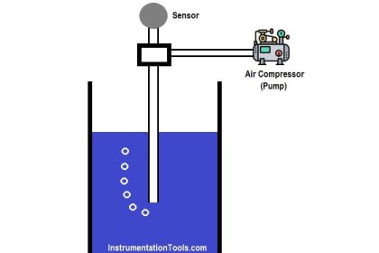
Displacer level sensor use Archimedes’ Principle to detect liquid level by continuously measuring the weight of a displacer rod immersed in the process liquid.

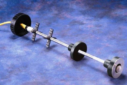
The displacer is cylindrical in shape with a constant cross-sectional area and made long or short as required. Standard heights range from 14 inches to 120 inches.

As liquid level increases, the displacer rod experiences a greater buoyant force, making it appear lighter to the sensing instrument, which interprets the loss of weight as an increase in level and transmits a proportional output signal.

As liquid level decreases, the buoyant force on the displacer rod decreases with a corresponding weight increase which is interpreted as decreasing level by the level sensor which then give a corresponding signal output.

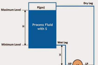
Shown below is a typical displacer level sensor installation:

Displacer Level Sensor

Although the basic theory of operation has been outlined above, in a practical displacer level sensor, the construction is engineered to achieve the desired measurement objective with sophisticated electronic circuitry.

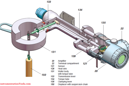
In these types of displacer level sensors, the displacer is attached to a spring which restricts its movement for each increment of buoyancy (i.e. level change).

A transmitter incorporating a Linear Variable Differential Transformer (LVDT) is used to track the rise and fall of the displacer rod as liquid level changes. Sophisticated electronics is then used to process the voltage signal from the LDVT into a 4-20mA output signal.

Archimedes’ Principle Applied to the Displacer

According to Archimedes’ Principle, the buoyant force on an immersed object is always equal to the weight of the fluid volume displaced by the object.

Suppose in a displacer level sensor, we have a cylindrical displacer rod with density, ρ, radius, r, length, L, and process fluid of density, У. In this installation, the length of the displacer rod is proportional to the liquid level being measured:

Volume of displacer rod, V=πr2L

shown in the diagram for the displacer level sensor installation above, when the vessel is full, the displacer rod is completely immersed in the process fluid hence the volume of process fluid displaced is V=πr2L. When the level of the vessel is empty or minimum, volume of process fluid displaced is V = 0

Hence:

When vessel is full, buoyant force on displacer rod is given by:

Buoyant Force = weight of process fluid displaced

= πr2LУg (g = acceleration due to gravity)

Real weight of displacer = πr2Lρg

Net weight of displacer sensed by the LVDT, transmitter and associated electronics when vessel is full is:

= πr2Lρg−πr2LУg=πr2Lg(ρ–У)=Vg(ρ–У)

As can be seen above, the net weight sensed by the LVDT is proportional to the difference in density of the displacer rod (ρ) and that of the process fluid (У)

Therefore, the displacer rod must have a higher specific gravity than that of the liquid level being measured and have to be calibrated for the specific gravity of the liquid.

Typical specific gravity range for liquids where the displacer level sensor is applied is in the range of 0.25 to 1.5. Another point worth mentioning is that the range of the displacer level instrument is dependent only upon the length (L) of the displacer rod specified for the given application.

When vessel is empty or level is minimum,

Buoyant force on displacer = 0

Hence, weight sensed by the LVDT is =πr2Lρg

The LVDT registers a voltage signal at minimum vessel level and outputs a corresponding signal. The displacer length is determined by the operating range (span) specified, the specific gravity, pressure, and temperature of the process fluid. The diameter and weight are factory calculated to ensure correct operation and providing accurate 4-20mA output.

Areas of Application

The displacer level sensor is used in level measurement applications such as knock- out pots, condensate drums, separators, flash vessels, storage vessels and receiver tanks.

Don't Miss Our Updates
Be the first to get exclusive content straight to your email.
We promise not to spam you. You can unsubscribe at any time.
Invalid email address
You've successfully subscribed !

Continue Reading

What is a Level Switch? Types of Level Switches
Servo Level Transmitter Principle
Hybrid Level Measurement Principle, Selection, Installation, Limitations and Calibration
DP Transmitters Level Measurement Principle Video
Radiation based Level Sensor Principle
Effects of Symmetric and Asymmetric Capillary Tube Pressure Measurement
Share This Article
Facebook Whatsapp Whatsapp LinkedIn Copy Link
Share
Leave a Comment

Leave a Reply Cancel reply

Your email address will not be published. Required fields are marked *

Stay Connected

128.3kFollowersLike
69.1kFollowersFollow
210kSubscribersSubscribe
38kFollowersFollow

Categories

Explore More

How Tilt Level Switch Works ?
Basics of DP Level Measurement
Closed Tank Level Measurement using DP Transmitters
Remote Seal Differential Pressure Transmitters Principle
Difference between Transparent Level Gauge and Reflex Level Gauge
Differential Pressure Level Transmitter Errors
Open Tank DP Level Transmitter Calculations
DP Level Measurement Problems

Keep Learning

Magnetic Float Level Sensor Principle

Magnetic Float Level Transmitter Working Principle

Bubble Tube Level measurement

Bubble Tube Level Measurement Principle

Level Gauge Interface Measurement

Level Gauge Interface & Temperature Problems

Displacement Level Transmitter in situ calibration

Displacer (buoyancy) Level Transmitter Principle, Limitations, Design, Installation & Calibration

Surface Detector Level Measurement System

Surface Detector Level Gauges (Plumb-bob)

Closed-tank-DP-Level-Transmitter-with-wet-leg-elevation-zero-direct-mount-Calibration

Closed tank DP Level Transmitter with wet leg elevation zero direct mount Calibration

potentiometric level measurement principle

Potentiometric Level Measurement Principle

Zero Suppression in level Measurement

Zero Suppression and Zero Elevation Calculations

Learn More

Analog Electronics Objective Questions

Analog Electronics Objective Questions – Set 11

Safety PLC System

SIS Maintenance – Safety Instrumented System

Electrical Machines Questions and Answers

DC Machine Quiz

Control valve positioner calculation

Calculate Control Valve Stem Position

PLC Circuit Answers

PLC connected to Three Pushbutton Switches

Basic Requirements of Sizing the Control Valves

Basic Requirements of Control Valves Sizing

Analyzer Sampling System

Gas Analyzer Sampling System

S84 - IEC 61511 Standard for Safety Instrumented Systems

S84 / IEC 61511 Standard for Safety Instrumented Systems

Menu

  • About
  • Privacy Policy
  • Copyright

Quick Links

  • Learn PLC
  • Helping Hand
  • Part Time Job

YouTube Subscribe

Follow US
All rights reserved. Reproduction in whole or in part without written permission is prohibited.
Welcome Back!

Sign in to your account

Username or Email Address
Password

Lost your password?