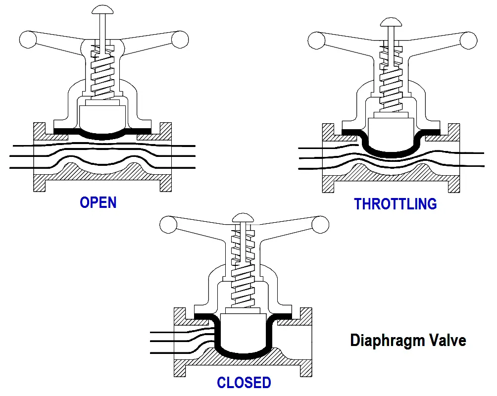
A diaphragm valve is a linear motion valve that is used to start, regulate, and stop fluid flow. The name is derived from its flexible disk, which mates with a seat located in the open area at the top of the valve body to form a seal.
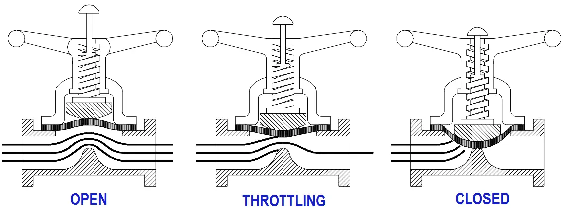
A diaphragm valve is illustrated in below Figure.
Figure : Straight Through Diaphragm Valve
Diaphragm valves are, in effect, simple “pinch clamp” valves. A resilient, flexible diaphragm is connected to a compressor by a stud molded into the diaphragm.
The compressor is moved up and down by the valve stem. Hence, the diaphragm lifts when the compressor is raised. As the compressor is lowered, the diaphragm is pressed against the contoured bottom in the straight through valve illustrated in above Figure or the body weir in the weir-type valve illustrated in below Figure.
Diaphragm valves can also be used for throttling service. The weir-type is the better throttling valve but has a limited range. Its throttling characteristics are essentially those of a quick opening valve because of the large shutoff area along the seat.
A weir-type diaphragm valve is available to control small flows. It uses a two-piece compressor component. Instead of the entire diaphragm lifting off the weir when the valve is opened, the first increments of stem travel raise an inner compressor component that causes only the central part of the diaphragm to lift.
This creates a relatively small opening through the center of the valve. After the inner compressor is completely open, the outer compressor component is raised along with the inner compressor and the remainder of the throttling is similar to the throttling that takes place in a conventional valve.
Diaphragm valves are particularly suited for the handling of corrosive fluids, fibrous slurries, radioactive fluids, or other fluids that must remain free from contamination.
Diaphragm Valves Construction
The operating mechanism of a diaphragm valve is not exposed to the media within the pipeline. Sticky or viscous fluids cannot get into the bonnet to interfere with the operating mechanism.
Many fluids that would clog, corrode, or gum up the working parts of most other types of valves will pass through a diaphragm valve without causing problems.
Conversely, lubricants used for the operating mechanism cannot be allowed to contaminate the fluid being handled. There are no packing glands to maintain and no possibility of stem leakage.
There is a wide choice of available diaphragm materials. Diaphragm life depends upon the nature of the material handled, temperature, pressure, and frequency of operation.
Some elastomeric diaphragm materials may be unique in their excellent resistance to certain chemicals at high temperatures.
However, the mechanical properties of any elastomeric material will be lowered at the higher temperature with possible destruction of the diaphragm at high pressure. Consequently, the manufacturer should be consulted when they are used in elevated temperature applications.
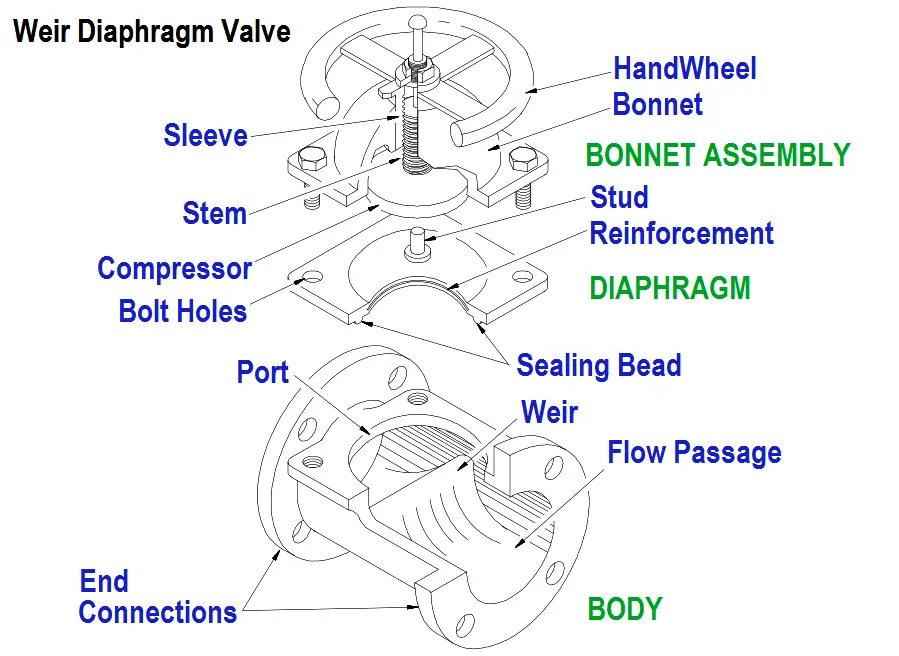
Figure : Weir Diaphragm Valve
All elastomeric materials operate best below 150°F. Some will function at higher temperatures. Viton, for example, is noted for its excellent chemical resistance and stability at high temperatures.
However, when fabricated into a diaphragm, Viton is subject to lowered tensile strength just as any other elastomeric material would be at elevated temperatures.
Fabric bonding strength is also lowered at elevated temperatures, and in the case of Viton, temperatures may be reached where the bond strength could become critical.
Fluid concentrations is also a consideration for diaphragm selection. Many of the diaphragm materials exhibit satisfactory corrosion resistance to certain corrodents up to a specific concentration and/or temperature.
The elastomer may also have a maximum temperature limitation based on mechanical properties which could be in excess of the allowable operating temperature depending upon its corrosion resistance. This should be checked from a corrosion table.
Diaphragm Valve Stem Assemblies
Diaphragm valves have stems that do not rotate. The valves are available with indicating and non-indicating stems.
The indicating stem valve is identical to the non-indicating stem valve except that a longer stem is provided to extend up through the handwheel.
For the non-indicating stem design, the handwheel rotates a stem bushing that engages the stem threads and moves the stem up and down. As the stem moves, so does the compressor that is pinned to the stem. The diaphragm, in turn, is secured to the compressor.
Diaphragm Valve Bonnet Assemblies
Some diaphragm valves use a quick-opening bonnet and lever operator. This bonnet is interchangeable with the standard bonnet on conventional weir-type bodies.
A 90° turn of the lever moves the diaphragm from full open to full closed. Diaphragm valves may also be equipped with chain wheel operators, extended stems, bevel gear operators, air operators, and hydraulic operators.
Many diaphragm valves are used in vacuum service. Standard bonnet construction can be employed in vacuum service through 4 inches in size. On valves 4 inches and larger, a sealed, evacuated, bonnet should be employed. This is recommended to guard against premature diaphragm failure.
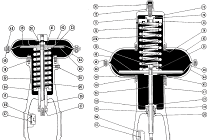
Sealed bonnets are supplied with a seal bushing on the non-indicating types and a seal bushing plus O-ring on the indicating types. Construction of the bonnet assembly of a diaphragm valve is illustrated in above Figure.
This design is recommended for valves that are handling dangerous liquids and gases. In the event of a diaphragm failure, the hazardous materials will not be released to the atmosphere. If the materials being handled are extremely hazardous, it is recommended that a means be provided to permit a safe disposal of the corrodents from the bonnet.
