Suppose an electronic pressure transmitter has an input range of 0 to 100 PSI and an output range of 4 to 20 mA. When subjected to a 5-step up-and-down “As-Found” calibration test, it responds as such:
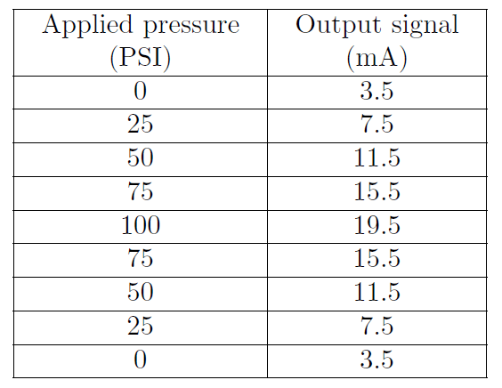
Sketch this instrument’s ideal transfer function on the graph below, along with its actual transfer function graph based on the measured values recorded above. Then, determine what kind of calibration error it has (zero shift, span shift, hysteresis, and/or linearity):
Finally, identify how this calibration error might be corrected. What steps or procedures would you follow to rectify this problem?
How might the other three calibration errors appear when graphed?
What purpose is served by doing an up-and-down test? Why not just check the instrument’s response in one direction only?
Which constant in the y = mx + b linear equation represents zero, and which represents span?
This instrument has a zero shift error, but not a span shift or linearity error.
A zero error is usually correctable by simply adjusting the “zero” screw on an analog instrument, without making any other adjustments.
Span errors, by contrast, usually require multiple adjustments of the “zero” and “span” screws while alternately applying 0% and 100% input range values to check for correspondence at both ends of the linear function.
Share your answers with us through below comments section.
Credits: Tony R. Kuphaldt
The conveyor sorting machine is widely used in the packing industries using the PLC program…
Learn the example of flip-flop PLC program for lamps application using the ladder logic to…
In this article, you will learn the STAR DELTA programming using PLC controller to start…
Lube oil consoles of rotary equipment packages in industrial process plants are usually equipped with…
Rotating equipment packages such as pumps, compressors, turbines need the lube oil consoles for their…
This article explains how to blink lights in ladder logic with a detailed explanation video…


